This is the next article in the series about our "Flower Machine".
Pneumatics means using compressed air to perform mechanical work. Our Flower Machine actually works using pneumatics only! But why would you choose pneumatics? And what components are needed? In this blog post, we will give an overview of pneumatics and their relationship with automating manufacturing.
Pneumatics in Manufacturing
In automated manufacturing, the most basic requirement is something that moves. There are many ways to achieve movement of course, with different trade-offs each. Pneumatics is one of them and has some key features that make it a great fit for manufacturing:
- Pneumatics is dead simple to control. A simple switch and a solenoid valve is enough to make an axis move. No feedback loop or homing procedure required.
- Pneumatics is great for repeating the same movement again and again. Extend, retract, extend, retract. Manufacturing processes consist mostly of repetitive motion, so it naturally fits well.
- Pneumatics naturally moves linearly, along an axis. Compare this to most electric motors which rotate and need an extra mechanism to convert the rotation into a linear movement.
- Pneumatics has minimum moving parts which makes it very robust against environmental influences. Even in dirty processes, it can be used without much trouble.
- And finally, because it is so simple, it is also much cheaper than the alternatives. At least in cost of acquisition.
As a demonstration, take a look at this video. Almost all the movements you can see are driven by pneumatics. This is the kind of application where pneumatics fits the requirements perfectly.
Giving an Overview
The hardest part for us when building our Flower Machine was that we did not know what there is to know. Sadly, information about pneumatics is sparse and there are few places to find an overview over all the pieces to the puzzle. Thus, instead of writing yet another article explaining the basics, we want to focus instead on giving an overview and showing where the detailed information can be found.
Between valves, pipe threads, and vacuum - we have a lot of ground to cover:
- The Basics
- Compressed Air Source
- Safety
- Types of Cylinders
- Directional Control Valves
- Connections: Tubing, Pipe Threads, and Fittings
- Controlling Speed
- Electro-Pneumatics
- Vacuum Suction Technology
- Pneumatic Schematics
1. The Basics
Nonetheless, we need to take a moment for the minimum basics to get started. Let's begin with arguably the most important part of a pneumatic system: the actuators, the parts that actually move.
These are called air cylinders. A cylinder has one or two chambers that can be filled with compressed air to make the cylinder move. For example, here is a double-acting cylinder. Double-acting means it has two chambers: One to extend and one to retract.
To control the air going into the cylinder, we need valves. More specifically, we need directional control valves. Theses valves can open to let air into one chamber of the cylinder and at the same time exhausting the air from the other chamber. Here is a schematic to visualize this concept. Red is the pressurized side and blue is the exhausting side. We will go into more detail about this later, when talking about the valves again.


And that's all you need to know for now. Of course the devil is in the details. But in the end, almost all pneumatic systems are just a more complicated version of this.
If you want a more thorough explanation of the basics, have a look at these resources:
- How a Industrial Pneumatic Systems Works - YouTube [VIDEO]
- (Pneumatics, Pneumatic Control and Electropneumatics explained - YouTube [VIDEO])
2. Compressed Air Source
Before doing anything with pneumatics, compressed air is needed. Compressed air is usually generated by a compressor. From there, it passes through a filter to remove moisture and particles. Valves and cylinders will wear out quickly if the air is not clean.
Next, it enters a regulator where it is reduced to a stable operating pressure. As the pressure has direct impact on the speed and force of the air cylinders, it is important that supply pressure is well regulated and does not fluctuate too much.
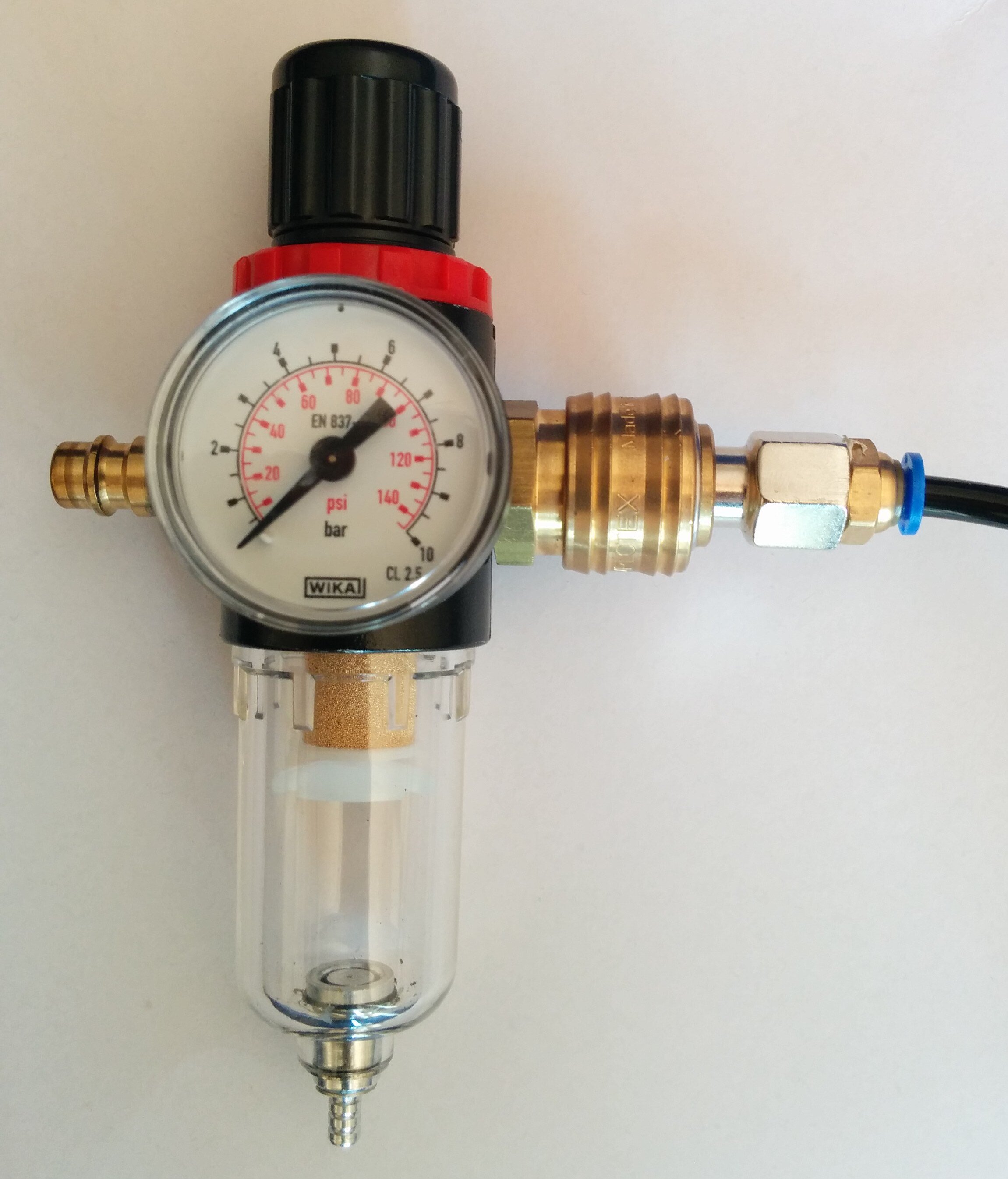
Commonly, the filter and regulator can be combined into a single FR-unit or filter-regulator. A manometer/pressure gauge is attached so you can keep an eye on the actual pressure in the system. Here is an example of such a unit:
Typical operating pressure of pneumatic systems (i.e. after the regulator) is around 4 to 6 bar. The general rule is to keep the pressure as low as possible as air consumption is directly proportional to it. Compressed air is a quite expensive source of energy so keeping consumption low is important.
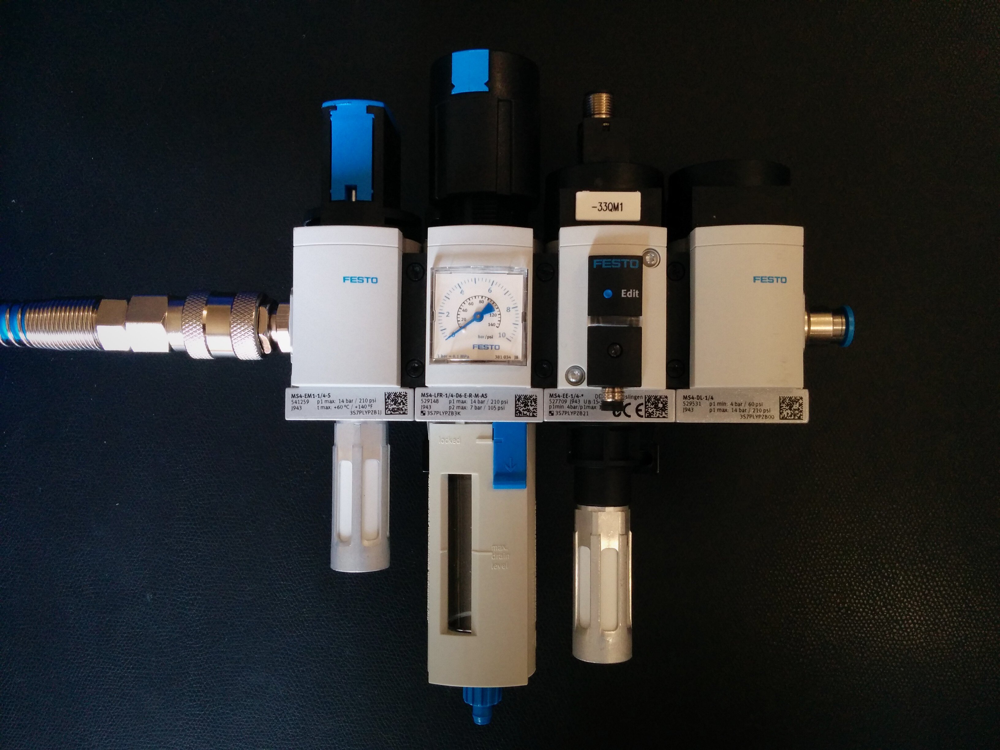
Maintenance Unit
For any real application, the filter-regulator is just one part of the so-called maintenance unit. Other componenents which are usually found in a maintenance unit might be:
- A manual shut-off valve to lock out the air supply during maintenance/repairs.
- An electrical shut-off valve so the air supply can be controlled automatically. Somethings this shut-off valve is safety rated so air pressure can be relieved immediately in the event of an emergency.
- A soft-start valve to slowly ramp up pressure.
More details about compressors, filters, and regulators are explained in the "How a Industrial Pneumatic Systems Works" video on YouTube.
3. Safety
Before diving in, we have to talk about safety. Pneumatic systems have a number of dangers that you need to be well aware of:
- Pneumatic actuators have quite a lot of force. Make sure that dangerous motions are only possible when nobody can get injured.
- Consider possible failures of the pneumatic system. Choose the correct valve type for each cylinder such that in the event of a sudden loss of electricity, the system still behaves as intended .
- Keep in mind that even without cylinders, compressed air is not without hazards. Air streaming out of an unsecured end of tubing will make it flail around violently. And the noise that is produced by the air can be loud enough to damage your ears permanently.
The whole topic of safety is quite complex. Ideally, you should make yourself familiar with the local regulations and standards for machine safety and adhere to their requirements. Don't take this blog post as any kind of safety advice.
4. Types of Cylinders
Let's start by going back to the air cylinders. There are many variants available.
First of all, the example above just showed a double-acting cylinder. These have two chambers and air is needed for movement in either direction.
There are also single-acting cylinders with only one air chamber. In place of the other chamber, a spring is used which automatically pushes the cylinder back as soon as the air chamber is no longer pressurized.
Beyond the method of control, there are also many different ways of how cylinders actuate, for different applications. We're going to give a short overview first and then leave you with some links to more detailed articles about air cylinders.
Basics Cylinders
So far, we have only looked at the most basic type: A linearly moving cylinder with a piston rod. In the real world, these cylinders come in many shapes and sizes. Here are a few:
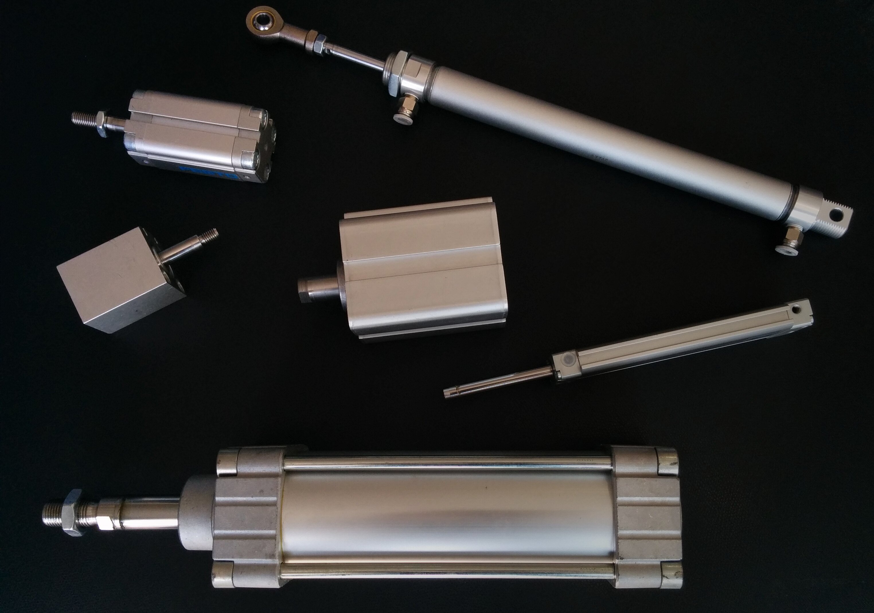
Such cylinders are essentially identified by two key parameters:
- The stroke length describes how far the piston can travel. This can be single-digit millimeters or up to a meter or two. Some cylinders even allow adjusting the stroke length.
- The piston diameter, in combination with the supply air pressure controls the force of the cylinder.
The bigger the diameter, the harder the cylinder can push or pull. The relationship is the following:

P is the supply pressure in pascals and D the diameter in meters. So a
cylinder with 32mm diameter at 4 bars of pressure will have a force of

So about the equivalent force of 33 kg. As you can see, the force scales quadratically with the diameter. It gets to dangerous amounts really fast.
Beyond this, there are usually several bells and whistles that you can choose from for your cylinder. For example, some cylinders have built-in cushioning at the end for a smooth stop. Without it, the movement can be very abrupt when going fast (which also decreases lifespan).
Guided Cylinders
One thing the cylinders above all have in common is that their rod/piston can rotate freely. For some applications this is not a problem but for many it is. That's why guided cylinders exist. These have additional rods parallel to the piston to prevent it from rotating.
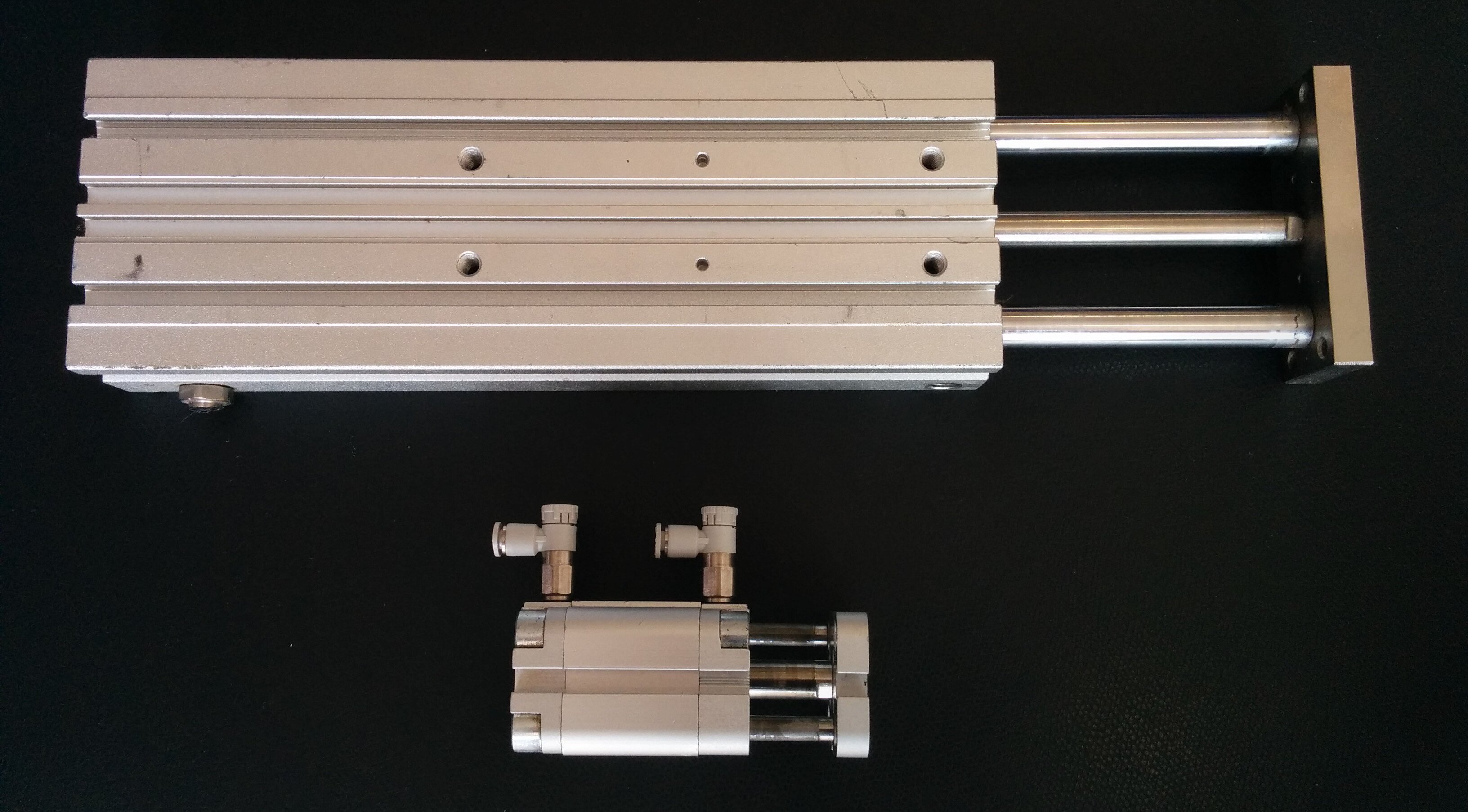
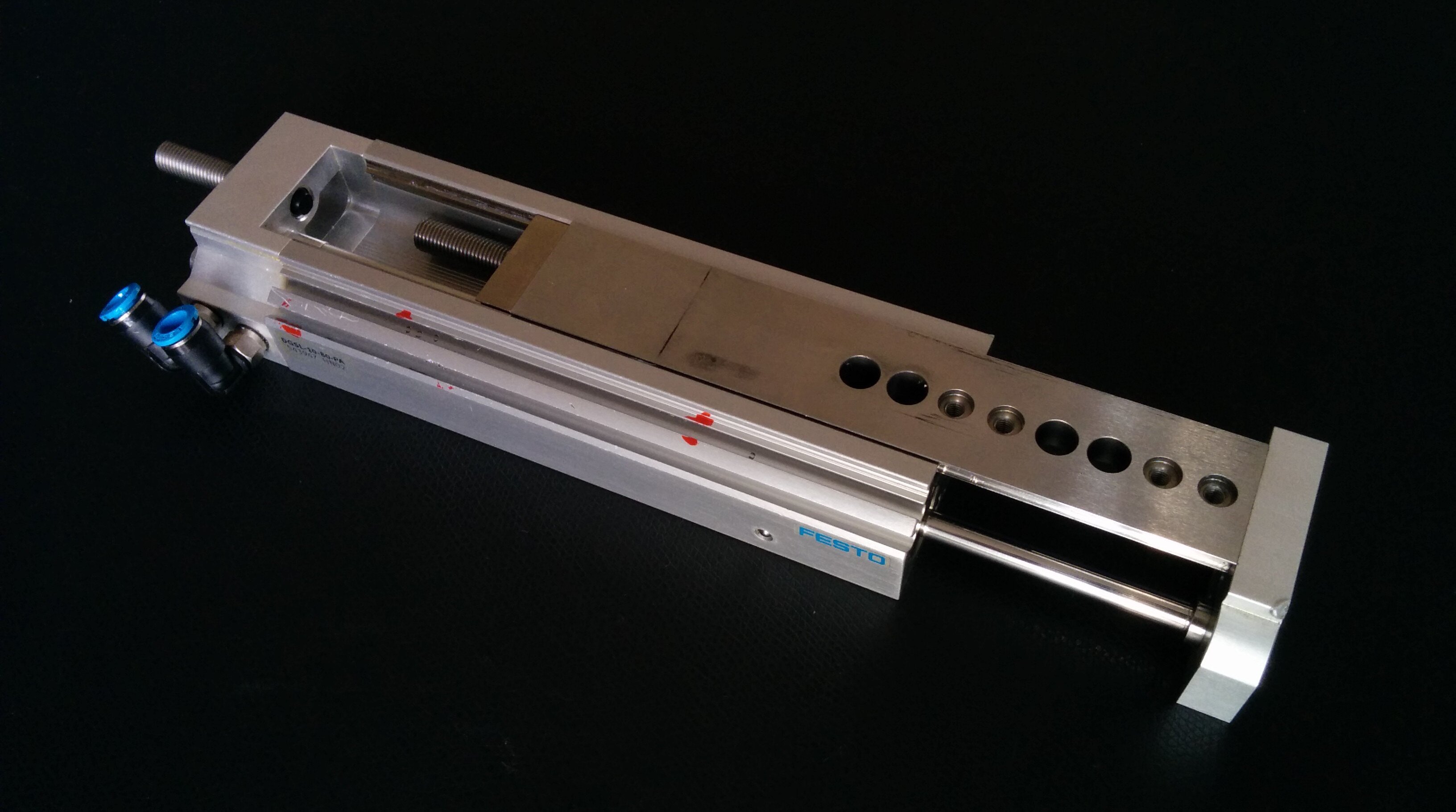
Slide Tables
Even guided cylinders are sometimes not precise enough. They usually resist rotation quite well but have play laterally. For applications where this is not acceptable, slide tables are an answer. These are, in the end, just a standard cylinder combined with linear rails for zero-play linear movement.
Rotating "Cylinders"
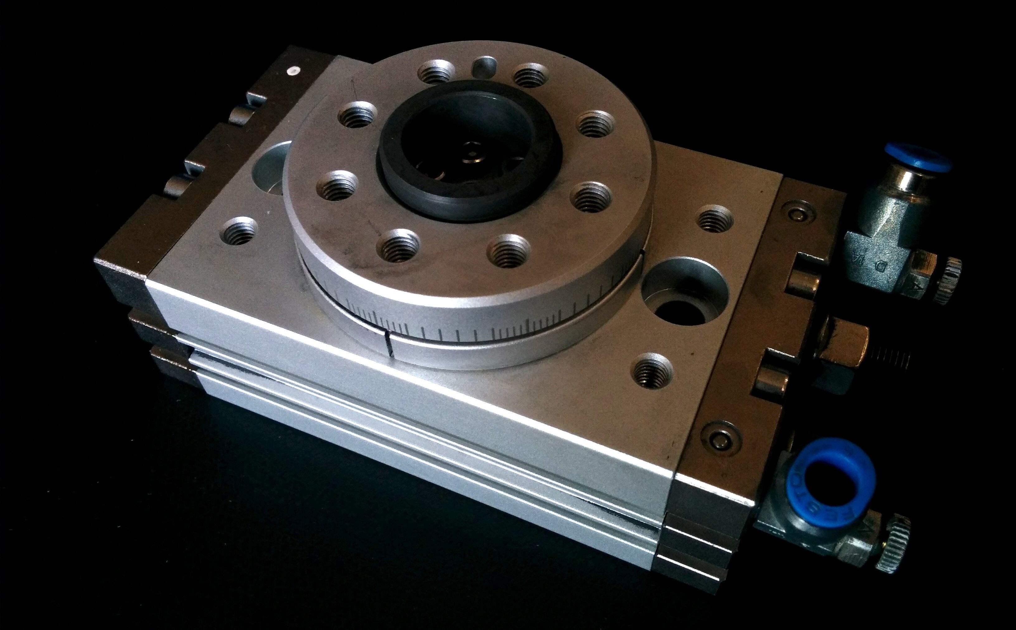
Even though quite a lot of movement is linear in factory automation, sometimes things must rotate as well of course. There are two types of rotating pneumatic actuators:
- rack-and-pinion type where a linear cylinder pushes a rack which rotates the pinion.
- vane type where a sealed vane rotates side to side.
Here you can see a typical rack-and-pinion type cylinder:
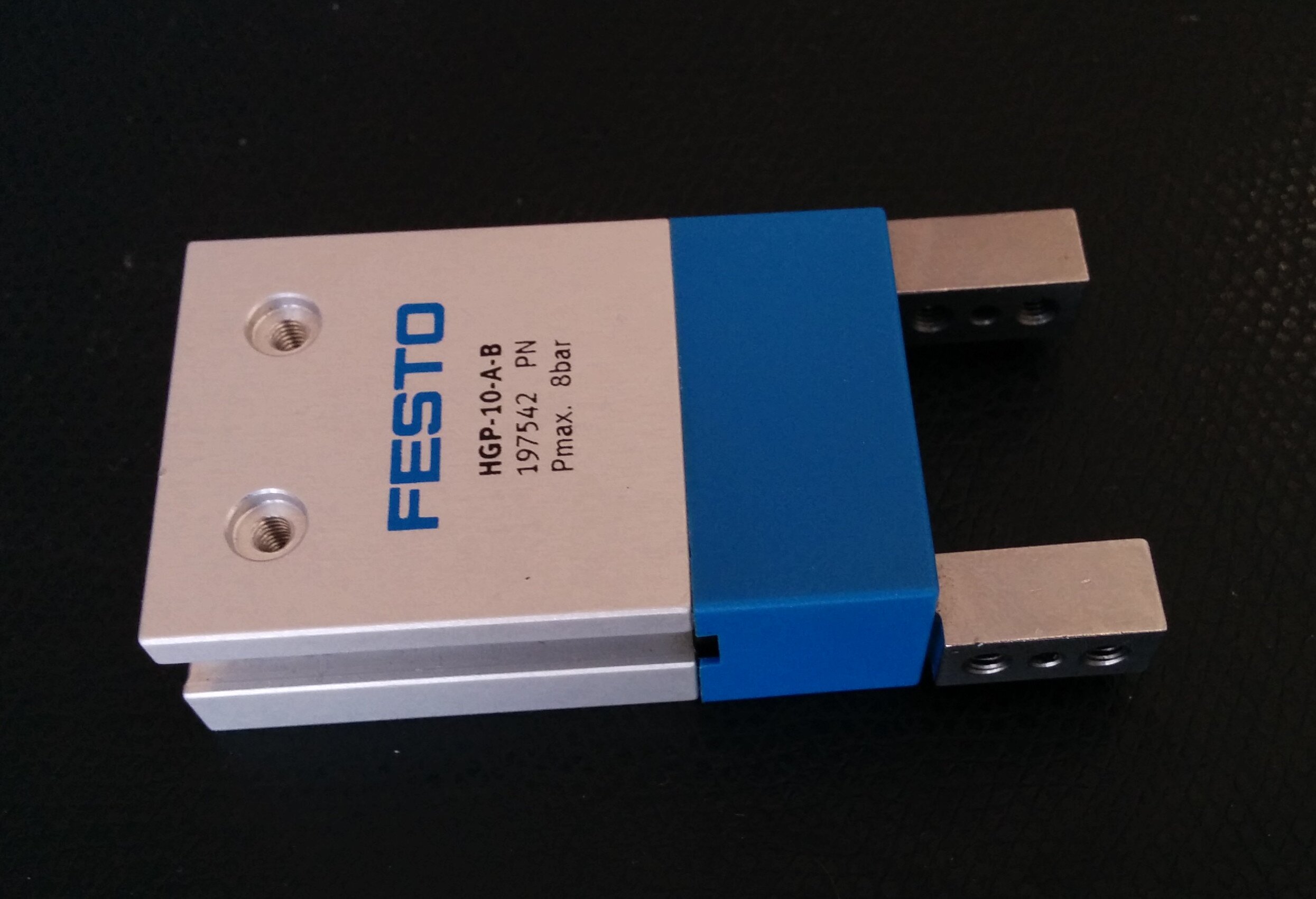
Grippers
Finally, because gripping parts is such a common task, special gripper cylinders are available. They have two fingers moving in opposite directions to grip onto something.
More about cylinders/actuators
This was a brief overview. For more information, maybe look at the following links:
- What is a Pneumatic Actuator? - RealPars
- Pneumatic Cylinder - Wikipedia
- 3 Main Types of Pneumatic Cylinders - Linquip
5. Directional Control Valves
To make an air cylinder do anything useful you need to control air flow into its chambers. In the end, any valve would do but specialized directional control valves are best for the job.
The valves itself also need to be controlled and in modern applications this is almost always done electrically, through use of a solenoid. Thus, these valves are often referred to as solenoid valves.
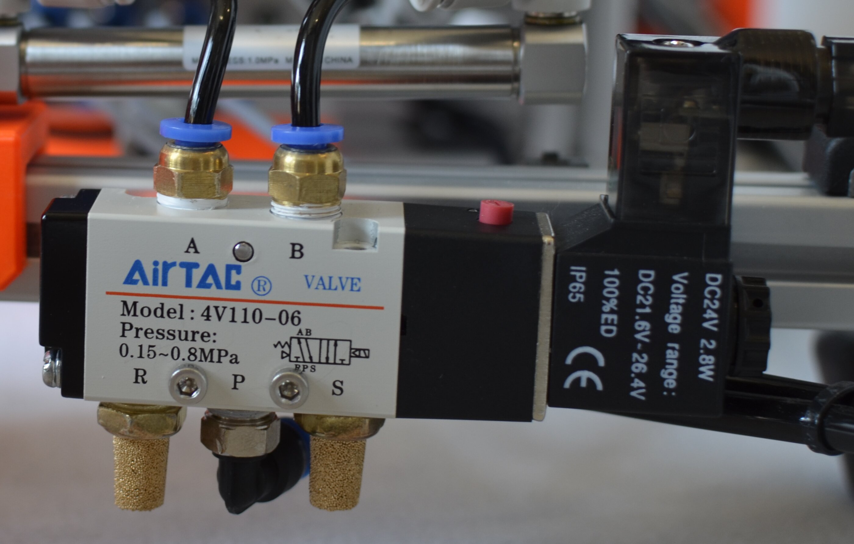
A DCV has a number of ports, through which air can flow in and out. Typically, there is the pressure port where supply pressure is connected, at least one working port where, for example, a cylinder is connected, and at least one exhaust port where air can exhaust when the valve deactivates.
The function of a valve is encoded in its schematic symbol. You can see all
the ports and, in each of the rectangles, how they are connected to each other
in each of the positions the valve can take. Further, you can see how each
"side" of the valve is actuated. Here, there is a solenoid (-MB1) on the
left side and a spring on the right side. This means the valve can be
activated using the solenoid and will return back to the original position by
spring force as soon as the solenoid deactivates.
The port-numbering/naming is standardized and works like this:
- The pressure port is
1or in older standardsP. - The working ports for the cylinders are even numbers
2,4orA,B. - The exhaust ports are odd numbers
3,5orR,S.
Silencers
One component that is visible in the picture and schematic above but wasn't talked about so far are silencers or mufflers. These reduce the noise from the exhausting air which would make quite a loud and sharp sound otherwise.
In the schematic, they are connected to the exhaust ports (3 and 5) and in the image, they are the gold-colored components on the bottom of the valve.
Finally, here are some further resources talking about the working principle of directional control valves in much more detail:
- What is a Spool Valve and How Does it Work? - RealPars
- How to Read a Spool Valve Schematic Drawing - RealPars
- What is a Directional Control Valve? - Upmation on YouTube [VIDEO]
- Directional Control Valve Working Animation - Upmation on YouTube [VIDEO]
Valve Terminals
In complex machinery, many of these valves will be needed. Because this requirement is so common, special equipment exists to organize a large amount of valves. This is called a valve terminal or valve manifold.
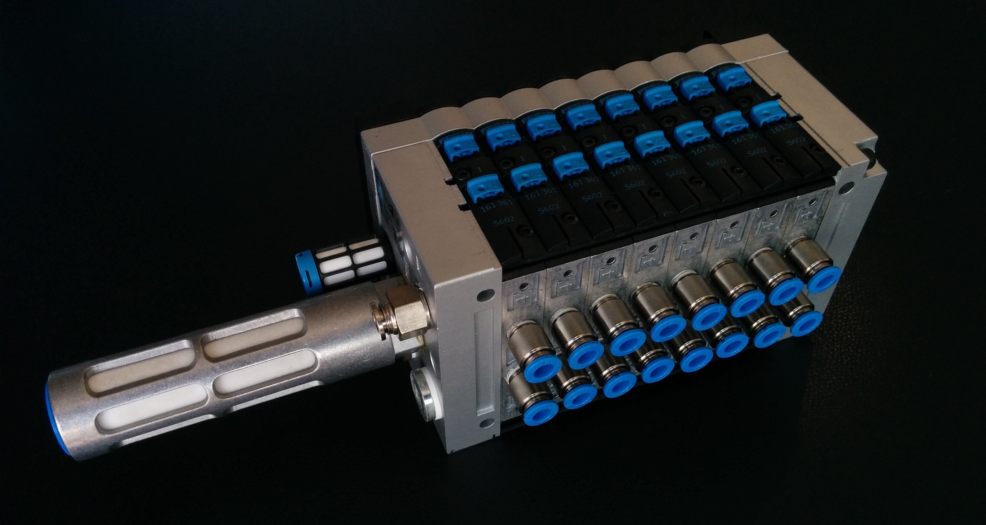
These valve terminals allow organizing a large amount of valves neatly, supplying each one with the supply pressure, and routing away all the exhaust air. Usually, they also bring an electrical terminal to control all the solenoids using a single connection to an industrial bus network (e.g. ProfiBus, Ethernet/IP, IO-Link).
And if you're curious, the large component sticking out the left side is the silencer for the combined exhaust air from all the valves.
6. Connections: Tubing, Pipe Threads, and Fittings
Cylinders, valves, and all other components don't have much use on their own. To make them useful, they need to be connected to each other, to form a pneumatic circuit.
Pneumatic Tubing
This is done using pneumatic tubing, which directs air from one component's port to another's.
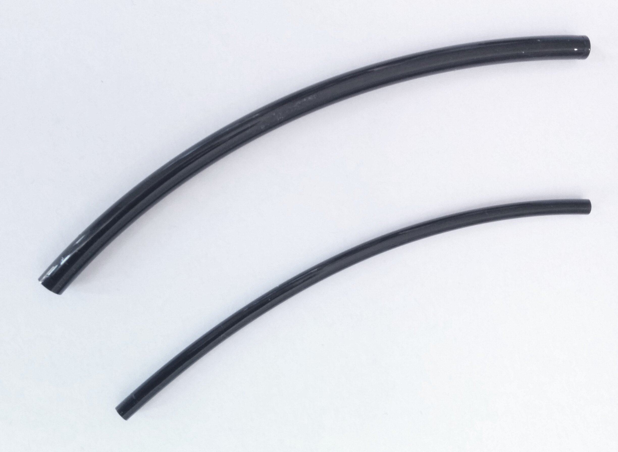
This tubing comes in many different materials and diameters. Importantly, the tubing is dimensioned by it's outside diameter. Common and cheapest is PU tubing. The most common diameters (outside US) are 4mm, 6mm, 8mm, 10mm, 12mm.
Pipe Threads
But even that is not enough. How do you connect the raw tubing ends to a valve or cylinder? The answer is complicated... But generally, the component's ports have an inner thread where an "adapter piece", called a fitting, can be screwed in. The threads here are a science in themselves. These are not e.g. standard metric threads but so-called pipe threads. They come in many variations. We'll try to clear things up a bit:
First of all, there are two main variants: parallel (straight) threads and tapered threads
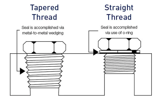
Image from www.thehopegroup.com/blog
As you can see, the important difference is the way the seal is accomplished. For tapered threads, it is common to have an additional sealing agent on the threads - often times this means wrapping thin PTFE-tape around it.
With the diameters and thread pitch, things start to get complicated: The Americans have, as always, their own system. Fortunately, the rest of the world has mostly come to a common standard based on the originally British BSP thread types. For all the gory details, there's existing resources you can have a look at:
- Thread Type Guide NPT, BSP, JIS, SAE, Metric - Trimantec
- How to Identify PT/NPT/G/Metric thread - TOPO Automatic
For us, there are three important standards:
- PT (or BSPT) which is also denoted by an R prefix. This is a tapered thread type.
- BSPP or G which is the parallel equivalent.
- Metric parallel threads like
M5x0.8which are used for smaller diameters.
For R and G, the diameters are based on fractions of inches. For example
R1/8, R1/4, R3/8, etc. Again, the links above have more details about
them all. Your takeaway should be to double-check the thread type for all
equipment.
Fittings
Into the threaded ports, a fitting is inserted which has a mechanism to secure a pneumatic tube on the other side. By far the most common (and most convenient) type are push-connect fittings. To insert the tubing, you just push it into the fitting. That's it. And to release it again, you push on the plastic (or metal) ring and pull out the tube at the same time.
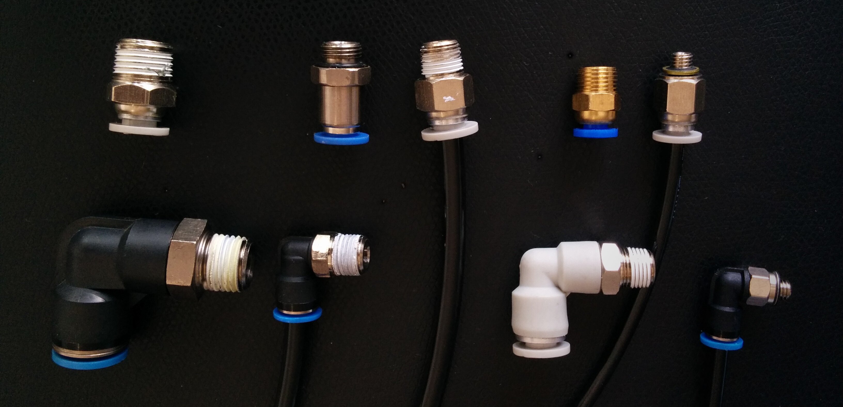
As you can see, these fittings come in straight or angled variants. Usually, you can get them connecting any of the thread-sizes to any of the common tubing diameters. As an example, a PC fitting for M5x0.8 to 4mm OD (outer diameter) tubing.
7. Controlling Speed
Equipped with all this knowledge so far, you'll be able to make a cylinder move. Except, it will move fast. So fast, that you can't even watch it travel. This is not terribly useful...
To slow the cylinder down to a more manageable speed, the air flow must be restricted. This is where throttle valves come in. The most common form is a valve that is a combination of a flow-restrictor and a check valve in parallel. This way, airflow is restricted in one direction, but the air can flow freely the other way.
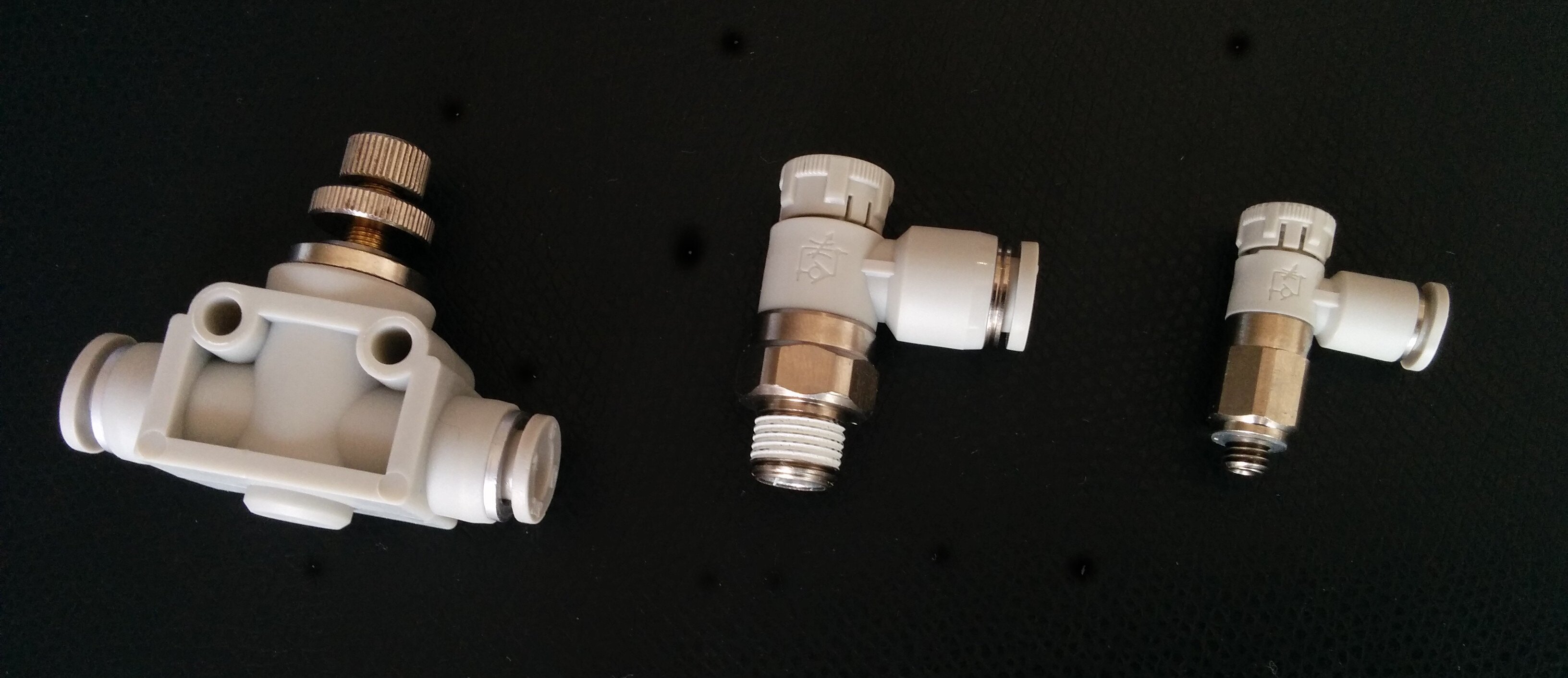
The most intuitive idea might be to restrict air flowing into the cylinder's chambers and let air escape from the other chamber freely (through the check-valve, note its direction in the image).

The cylinder can then only move as fast as the chamber can fill with air. While this works, it has a big disadvantage. As the chamber is slowly filling with air, the force the cylinder is pushing with will be quite low. Ideally, the cylinder should constantly push with its full force while traveling. This is especially important for achieving smooth motion due to the stick-slip effect.
To do this, we instead restrict the flow out of the opposite chamber while letting air flow freely into the first chamber. This means the piston is immediately experiencing the force of the full pressure and thus will be pushed forward with constant force.

In general, this is the configuration that is used most often. The only important thing to remember here is that it depends on one of the chambers starting out pressurized. If you're not careful, the first movement could still end up going at full speed (the solution is a soft-start valve which slowly ramps up the supply pressure when turning on a machine).
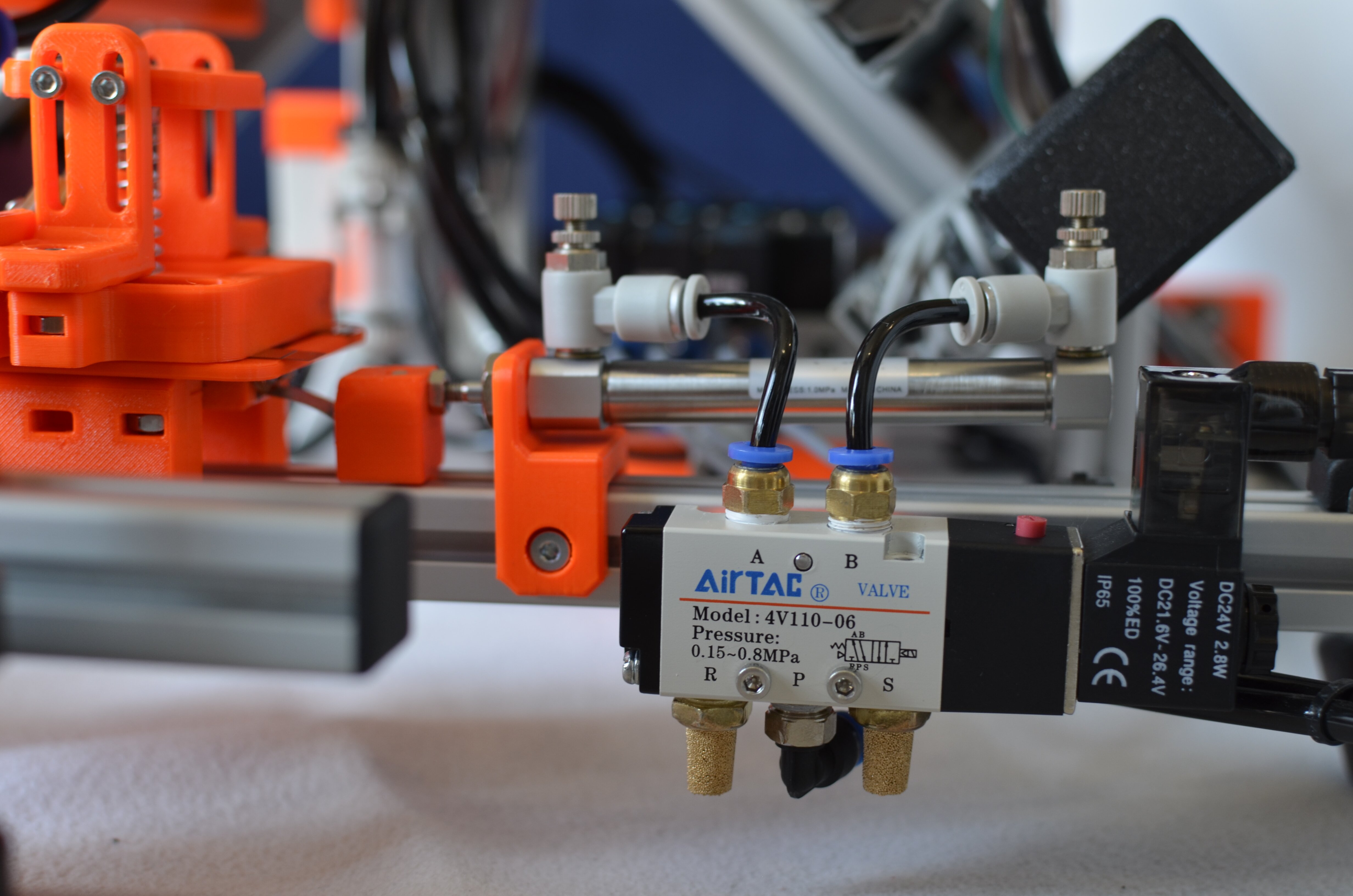
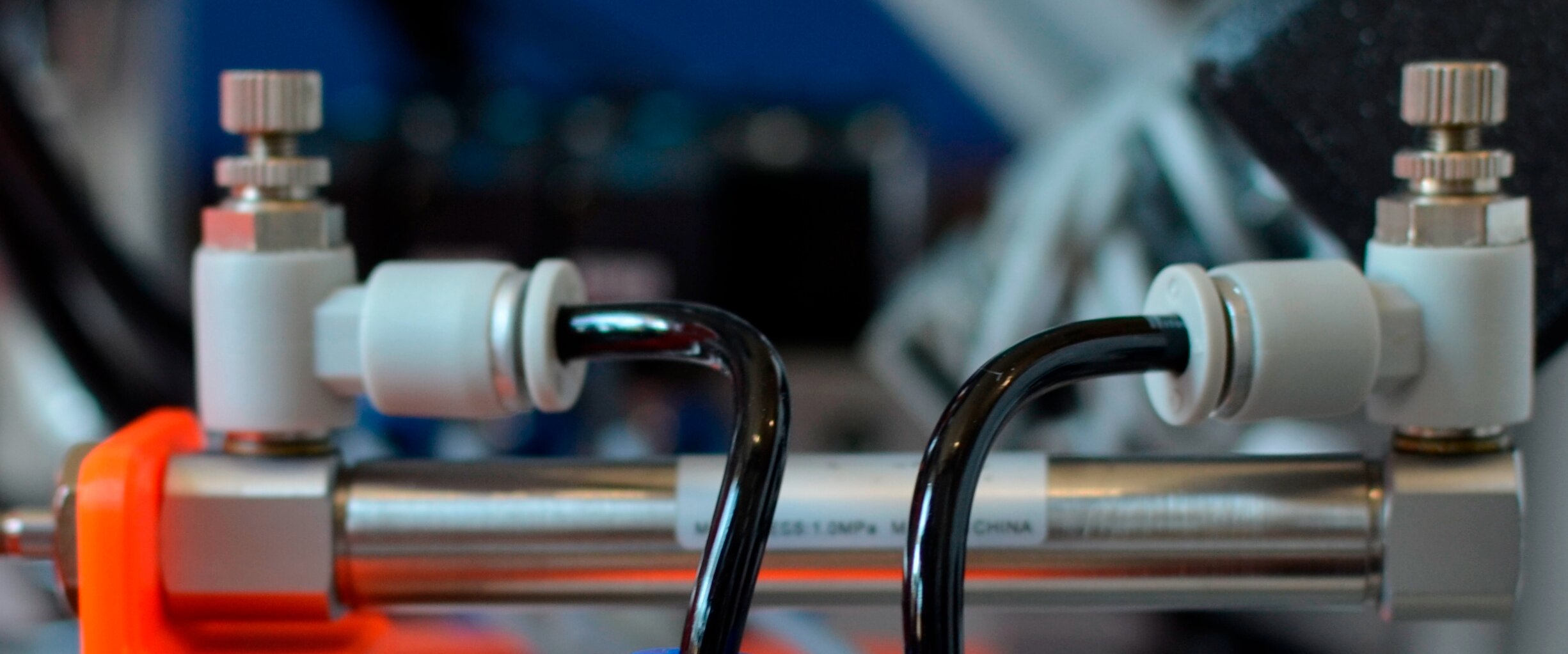
Now, going back to the images of throttle check valves from above, you might have noticed how some of them have push-connectors on both sides, but some have a threaded port. That's by design - these are intended to be screwed directly into the ports of a cylinder. This is a very common sight in pneumatic machinery: A cylinder with two throttle valves for controlling its speed:
8. Electro-Pneumatics
When talking about the DCVs (directional control valves) we've already talked about the electrically actuated variant, called a solenoid valve. As most pneumatic applications these days are electrically controlled, the whole field is often referred to as electro-pneumatics.
Controlling valves is only half of the story, though: The electrical brain of the machine also needs to have a way to sense the positions of each actuator to know when movements have completed.
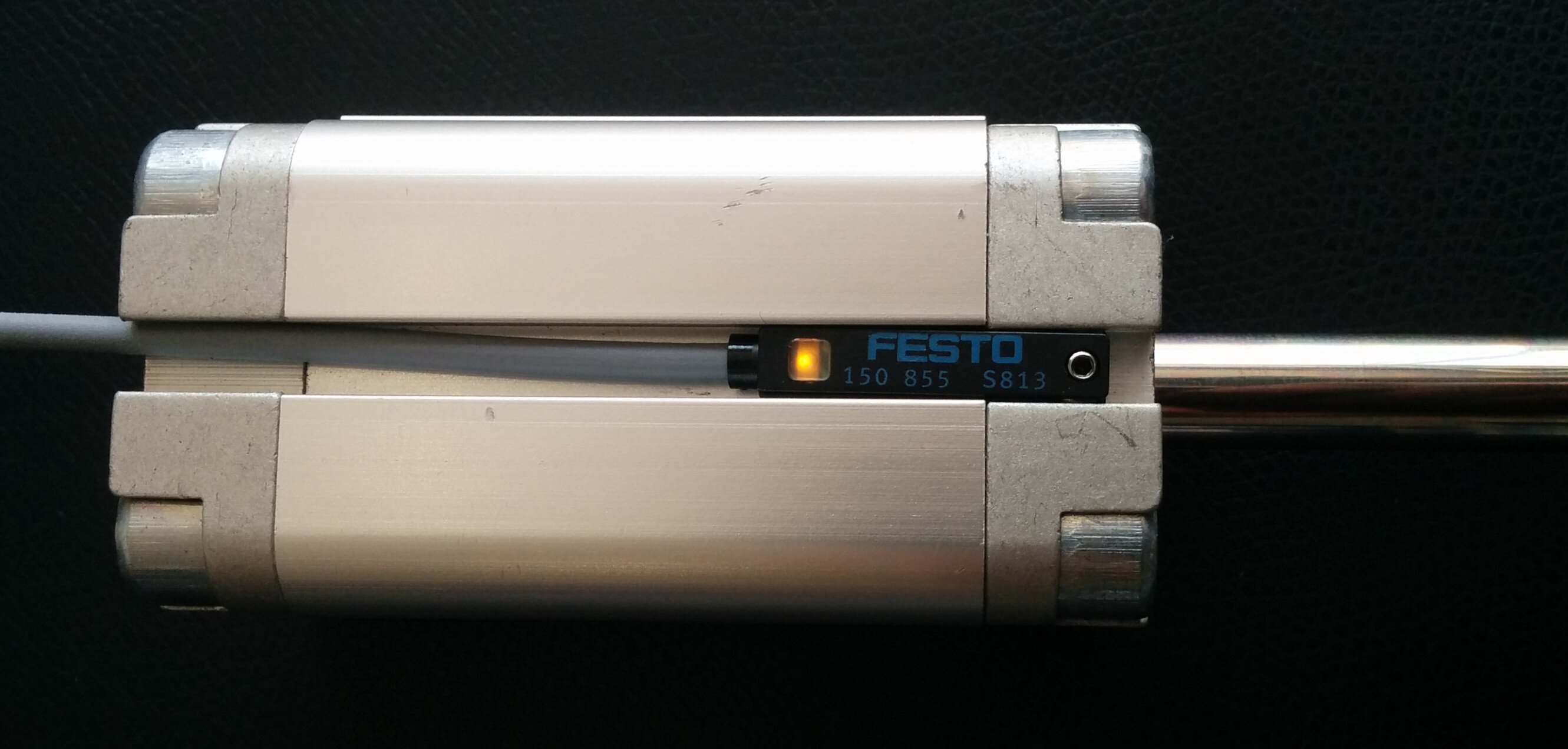
This is done using cylinder sensors which magnetically sense when the cylinder piston head has reached a certain position. A lot of cylinders come with small grooves along their side where the cylinder sensors can be slid in.
9. Vacuum Suction Technology
A seemingly completely different technology which is also a part of pneumatics is vacuum suction. Vacuum suction is heavily used in the industry to grip parts. That's because it is super simple to use and often much easier to implement than mechanical gripping.
Vacuum Ejectors
The first component you need is a vacuum ejector which produces the "negative" pressure. In fact, these actually work by using compressed air as well! The physical principle behind this is the venturi effect.
When compressed air is applied to the pressure port, the ejector sucks in air from the vacuum port.
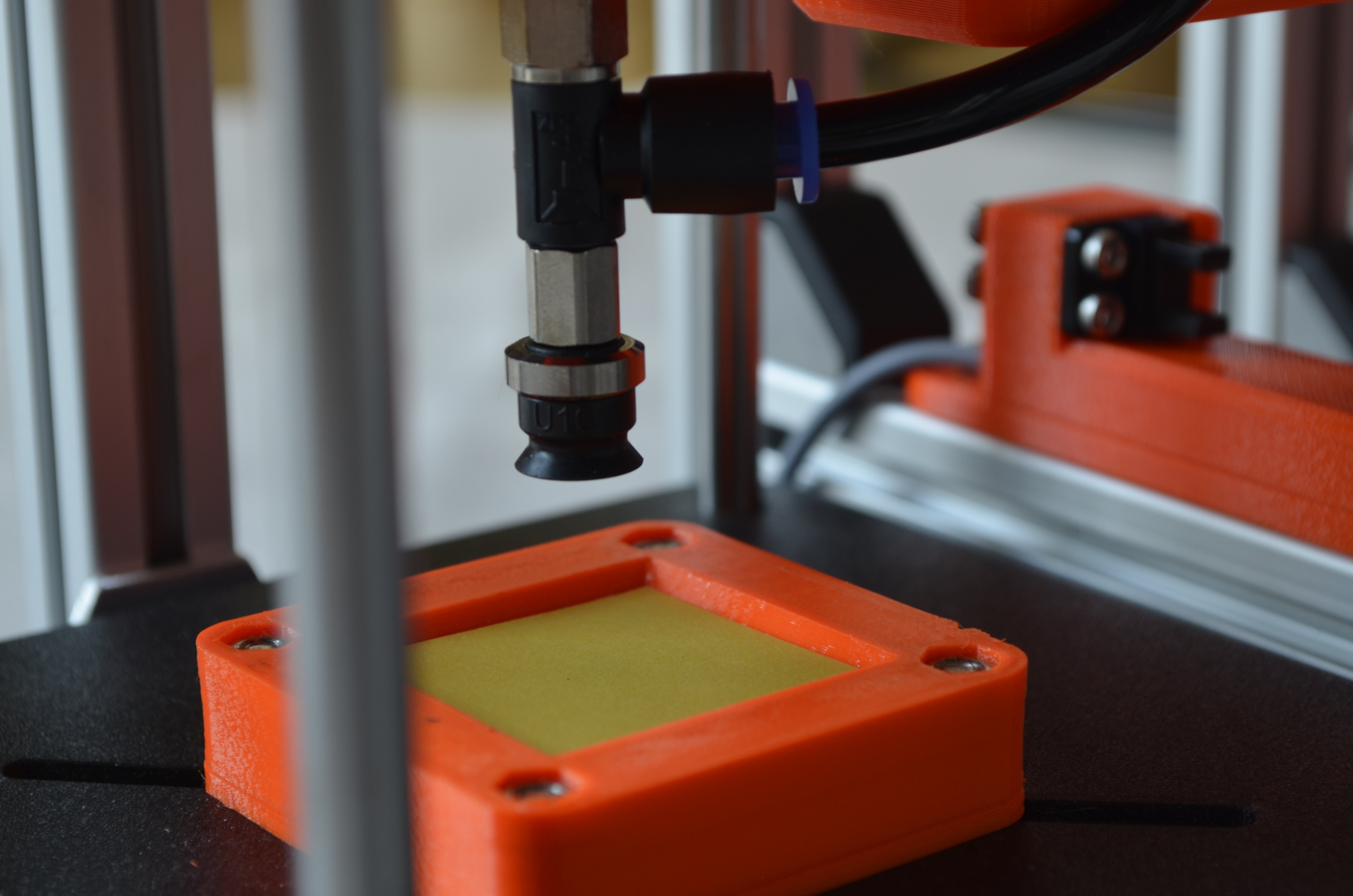
Suction Cups
On the vacuum port of the ejector, you'll need to connect a suction cup. These come in many different shapes and diameters, each specialized for a certain application.
Vacuum Filters
Finally, there are also special filter which may be connected between ejector and suction cup. Their purpose is to filter out large particles so they do not enter the vacuum ejector. This helps increase the lifespan of the device.
For more information about vacuum suction, here are some links:
- How VACUUM GENERATOR works? - Ms. Pneumatic on YouTube [VIDEO]
- Cup Selection Made Simple - Piab
10. Pneumatic Schematics
The last topic we're going to talk about is schematics of pneumatic circuits. As everywhere else, it is vital to document the connections and inner workings of a system. And thus, there exist standards for documenting pneumatic circuits as well.

In general, air flows from the bottom to the top - the compressor is the element at the very bottom and the actuators are at the very top.
To draw such circuits, a number of tools are available. Here are some free options if you want to play with them a bit:
- PneuDraw from SMC is an online tool for drawing pneumatic circuits.
- QElectroTech is a general tool for producing documentation of electrical, pneumatic, etc. systems. It is FOSS and it is what we used for our Flower Machine.
We're going to leave you with a page from the Flower Machine pneumatics documentation:

That's all for now. We hope this article was insightful and provided a good introduction into pneumatics. If you have any questions or you want to suggest changes/improvements to this page, feel free to contact us!
If you want, you can read the next blog-post in the Flower Machine series here: Poppy Logic Controller. Or head to the overview of all flower-machine posts.