This is the next article in the series about our "Flower Machine".
Of course a machine like this would be useless without any brain to control it. The industrial solution is called a PLC (Programmable Logic Controller). However a real PLC has a number of deal-breakers for us: It is expensive, full of proprietary software, and 99% of the time programming it is windows-only.
Thus I set out to build an alternative: Meet the Poppy Logic Controller - a custom PLC-like device which mimics the real thing, but on a budget.
In this post, I will go over the hardware side. A future post about the software/firmware will follow. You can also find all hardware design files and firmware sources on GitHub: https://github.com/Rahix/Poppy-Logic-Controller
What is a PLC, anyway? As always, Wikipedia wins for the one-sentence definition:
A programmable logic controller (PLC) or programmable controller is an industrial computer that has been ruggedized and adapted for the control of manufacturing processes, such as assembly lines, machines, robotic devices, or any activity that requires high reliability, ease of programming, and process fault diagnosis.
— Programmable logic controller on Wikipedia
Ignoring the software aspect (a blog-post about that will follow), we end up with a computer or microcontroller that can interface with industrial control systems and has been hardened to withstand the abuse of harsh industrial environments.
You cannot imagine what these things have to endure! Hot, cold, dirt, moisture, vibrations, interference of all kinds - all while running 24/7 and failure not being an option. In many places, every minute of downtime costs unimaginable amounts. So the hardware has to be built as robust as possible. Of course that does not come for free - some PLCs will set you back more than a car.
Lucky for us, the Flower Machine is a much more gentle environment. And that's why the industrial solution would be super overkill for this project. I also don't fancy programming the machine in some proprietary windows-only environment... Which also made a "real" PLC less attractive.
Yet, we need something. A plain microcontroller board à la Arduino/Raspberry Pi isn't quite enough: Their I/O is in the 3.3V to 5V range and doesn't allow for much current draw. The solenoid valves and sensors we are using all operate at 24V DC.
Instead of bodging together a mess of relay cards, microcontrollers, and whatever else, I decided it is a better idea to design a "proper" controller board. What does "proper" mean? Well, for the real world there is a standard for PLC hardware, the IEC 61131-2, which specifies the requirements (not to be confused with the famous 61131-3 for PLC programming languages). These requirements cover a lot of aspects of a PLC:
- Electrical characteristics and fault tolerance
- Robustness against EMI (electromagnetic interference)
- Environmental factors, such as vibration and temperature tolerance
- Safety requirements
My goal wasn't to be standard compliant - after all, most of those requirements don't matter for this use-case anyway. But knowing where I am deviating means I can consciously make the trade-off between robustness and a cheap device.
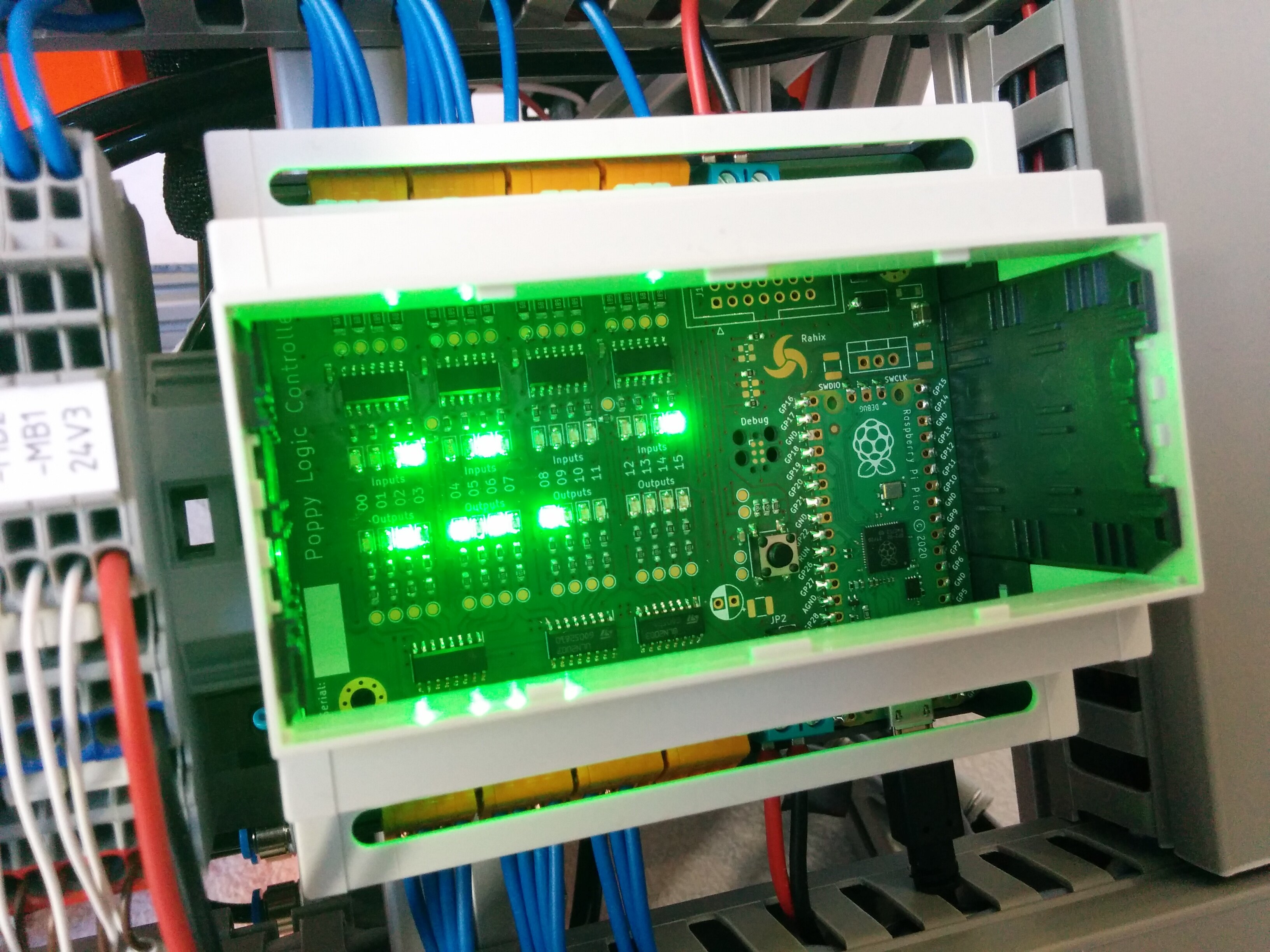
So I took the 61131-2 as inspiration and got to work. Here is the result, the Poppy Logic Controller:
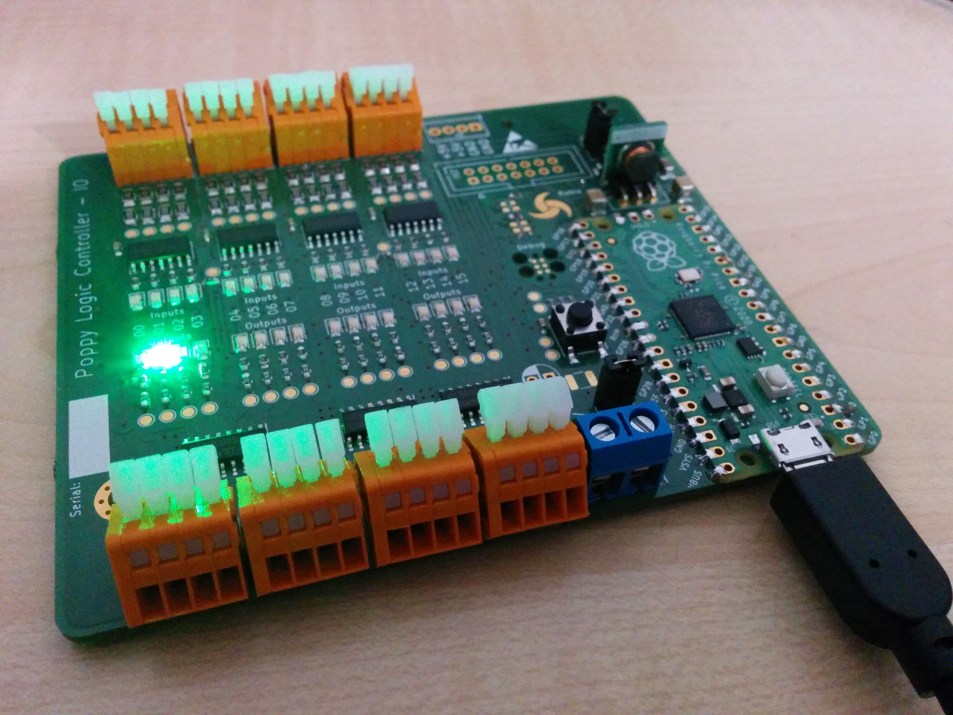
In the end, it isn't actually that much. It is just an I/O board with 16 inputs and 16 outputs. Each has an indicator LED and all I/Os are controlled over an I²C bus. At the moment, the brain is a Raspberry Pi Pico but the board is designed such that the Pico can be removed and a different controller can be connected via a pin-header.
24V Industrial I/O
The devices we want to control, the valves and sensors on the Flower Machine, are all rated for 24V DC. These days, I think this is the most commonly used scheme in control systems. To talk 24V DC, the IEC 61131-2 specifies characteristics for PLC inputs and outputs.
Sinking and Sourcing
The first thing to note is that there is two kinds of I/O: Sinking and Sourcing, also sometimes called NPN and PNP.
- In a sinking configuration, current flows into the input or output port.
- In a sourcing configuration, current flows out of the input or output port.
You always have to connect opposite pairs:
- If you have a sensor with a sourcing output, it must be connected to a sinking input on the PLC.
- A device with a sinking output can only be connected to a sourcing input.
The most intuitive configuration is sourcing outputs with sinking inputs. To illustrate, here is a circuit diagram:

- A switch or sensor will supply 24V to the sinking input of the PLC when it is turned on.
- A load is wired between the sourcing output of the PLC and 0V. The output will be raised to 24V by the PLC to activate the connected load. For example a solenoid.
The opposite scheme is sourcing inputs and sinking outputs:

Here, things are inverted and this might be a bit confusing at first:
- A switch or sensor will short its output to 0V when active so current flows out of the sourcing input of the PLC, through the sensor, to 0V. The input is effectively pulled down to 0V to activate it.
- The sinking output of the PLC does exactly the same thing: It will be internally connected to 0V when the output is active and thus a load must be wired between 24V and the sinking output.
These two articles explain the topic in more detail:
- Sinking and Sourcing PLC Inputs Explained - RealPars
- Sinking and Sourcing PLC Outputs Explained - RealPars
Poppy Inputs
The Poppy Logic Controller has 16 sinking inputs. The IEC 61131-2 defines 3 types of such inputs - I will only consider type-3. For this kind, at 24V DC, the standard boils down to the following requirements:
- A voltage less than 5V must be considered LOW (state 0).
- A voltage higher than 11V must be considered HIGH (state 1).
- Maximum current draw in either state is 15mA.
- Minimum current draw in HIGH state is 2mA.
That's just a simplified version, but it is good enough for this project. To approximate these requirements, I chose to go with the simplest and cheapest design possible: A resistor divider with a schmitt trigger. Note that I opted for a design without galvanic isolation in this case as well. The MCU, the Raspberry Pi Pico is cheaper than the isolators would be so the incentive for isolation wasn't really there...

As you can see, the voltage limits are not quite in spec. But that's okay, we won't use the controller in super high-noise environments or with extremely long signal cabling anyway.
Poppy Outputs
I chose to go with 16 sinking outputs. This is of course unusual in combination with the sinking inputs. But sinking outputs are so much easier to implement that it was the better choice anyway. The reason is that a sinking output is a low-side switch and these are cheaper and easier to get at the moment. Sinking outputs also allow driving devices with different supply voltages from the same controller as only the 0V potential must be shared between them.
I used ULN2003 chips which come with 7 low-side/NPN drivers each. A nice feature is the built-in flyback diode which means the Poppy Logic Controller can drive inductive loads without any concerns. Additionally, all outputs are fused at 300mA to protect against short circuits.

I/O Terminals
With all the input and output circuitry done, we need to connect to to the outside world now. For this, the Poppy Logic Controller needs I/O terminals. The straight-forward solution is screw-terminals but these take a lot of space and needing to tighten a screw for each connection is cumbersome.
A different kind of I/O terminals are spring-terminals. These are faster to wire up and there is no chance of under or over-tightening the connection. So I set out to find a spring-terminal that fits the project. It was actually quite challenging because a major constraint was compatibility with the enclosure. The enclosure I wanted to use was designed for screw-terminals and a spring-terminal that fits the space while still being "actuatable" was hard to find.
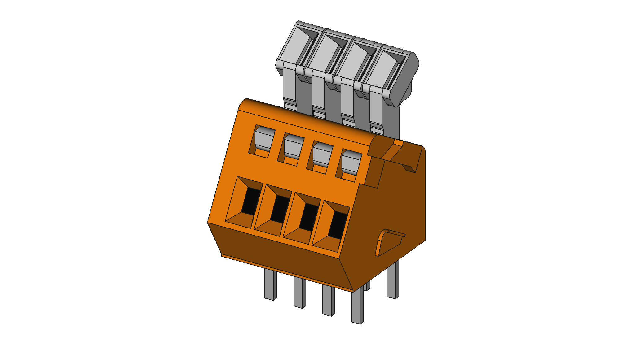
In the end, the WAGO 233-504 you can see above was a good enough match. The
only caveat is that this spring-terminal allows for a maximum wire size of
0.5mm². And at that size, only the plain conductor fits, no ferrules may be
used.
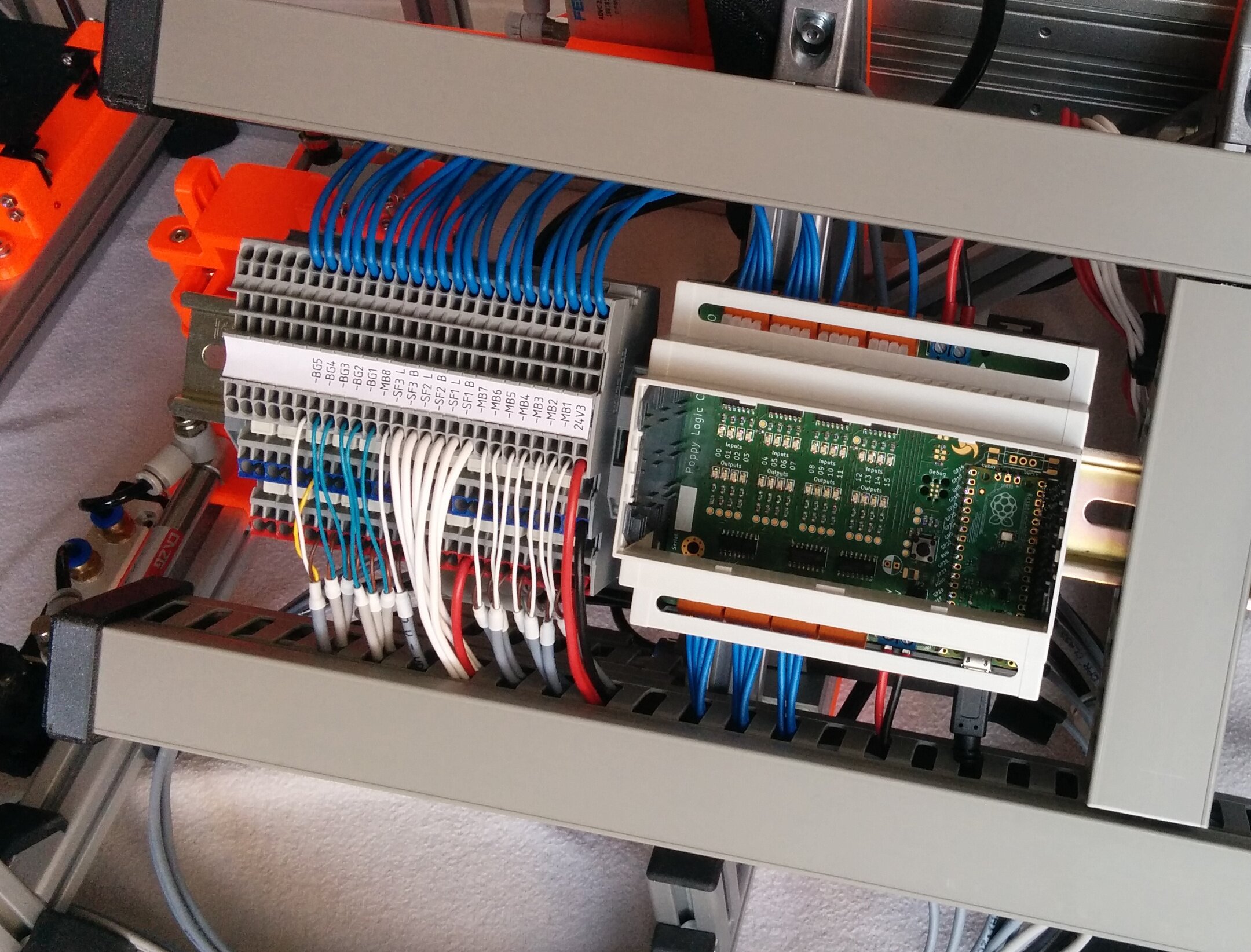
With the I/O terminals in place, let's wire it all up! Here you can see the Poppy Logic Controller with all I/O connected to a terminal block on the Flower Machine:
External Communication
The biggest feature that is missing from the Poppy Logic Controller in its current form is communication interfaces. There is the USB-port of the Raspberry Pi Pico, but nothing else. In hindsight, this was an unfortunate decision but as the project didn't have any communication requirements initially, I did not think about it too much.
In industrial automation systems, a large number of interfaces/bus-systems are used. Just look at the List of automation protocols on Wikipedia. Looking back, I should have at least added an RS-485 interface and, if possible, an ethernet port. These two allow a large number of common protocols to be supported, like Modbus RTU, Modbus TCP, EtherNet/IP, OPC/UA, and quite a few more.
For now, with the current hardware, in the worst case it should not be too difficult to add a small hardware mod to support a required protocol...
Build Your Own
Alright, convinced that you need your own now? I have published all design files for the Poppy Logic Controller so you can make that a reality. I want to briefly talk about some important details.
First things first, design files can be found here:
- Git Repository with KiCAD files (KiCAD 6) and firmware samples.
- Rendered Schematic
- Rendered BOM
- Rendered Interactive BOM
Parts
Supplier for almost all parts of this project was Reichelt Elektronik (no affiliation or sponsorship here, purely personal choice). I've tried reconstructing the BOM with all the Reichelt SKUs so you can painlessly get all you need from one place if you so desire. There is a column in the BOMs linked above with all the information you need.
Additional Components
Beyond the PCB's BOM, you will need a few more components. After all, you probably want the nice feeling of mounting your controller on a DIN-rail, don't you?
- The enclosure, which is an
APRA-NORM 449-360-65(ReicheltAPRA DB6 OBK) - Optionally, a lid for the enclosure, like
APRA-NORM 449-360-12(ReicheltAPRA 449-360-12). Also available in other colors. - A few (2) jumpers (Reichelt
JUMPER 2,54 SW)
Hardware Revisions
In the design files, you'll find the latest revision D. I suggest using that one although it is not exactly the version I have built. My (2) boards are built from revision B with one populated like revision C and one populated like revision D. You can read the changelog for details of the differences.
Programming It
So far, I have not released the software/firmware for this project. This will happen in due time, but for now you will have to program the Raspberry Pi Pico your own way. The design file repository contains a bare-bones firmware in Rust and MicroPython to get started. Check the READMEs for more info on that:
Not using the Pico
If you need a different microcontroller, you can drop the Raspberry Pi Pico and
instead solder the J12 header. You can then connect whatever controller you
desire and use the I²C bus (and interrupt lines) to interact with the I/O.
With all that, you should be set to build your own. If you are unsure or you have questions about anything, feel free to contact me to get it sorted out!
For us, the Poppy Logic Controller was nice for entering the field but we are already reaching the limits of I/O and connectivity. I suppose there will be a future board coming up to solve this...