This is the next article in the series about our "Flower Machine".
Back in the first post about the flower machine, we talked about what it is doing. It is time to introduce how it actually works. There are already some posts about very specific topics like pneumatics or the logic controller. Before writing more posts like these, I think it is a good idea to look at the bigger picture.
I want to walk through this by looking at the general anatomy of machines for factory automation. Even though ours is quite simple, I think it serves as a nice demonstration of what such a machine is made from. Before jumping in, a short reminder that both of us are not working in this area professionally so don't take everything we write as indisputable truths.
Ready? Well, before we can talk about the flower machine, we have to go back a bit further. Before there was a flower machine, there was a "product" to be produced and as the very first step, a process was needed for doing this production automatically.
Fold Pattern Creasing
As outlined in the first post about the project (read it here: Flower Machine), the goal was to crease a fold pattern into paper squares. This will allow later on, in a manual step, to very quickly collapse the premade folds into the flower model.
The most obvious starting point is with the question of how the fold pattern creasing is actually performed. When folding by hand, this is a very sequential process where each fold is created one after the other. This takes a lot of time and requires many different delicate movements. Not well suited for automated production.
Early on, before the whole project took shape, we experimented with the idea of creasing the fold patterns using a press. The paper is sandwiched between two die halves which hold sharp blades. By keeping the blade depth exactly right, instead of cutting the paper squares, we only score them, leaving a fold line. Blades in the bottom die create mountain folds, blades in the top die create valley folds. This way we can produce the entire pattern in a single movement of pressing the dies into the paper.
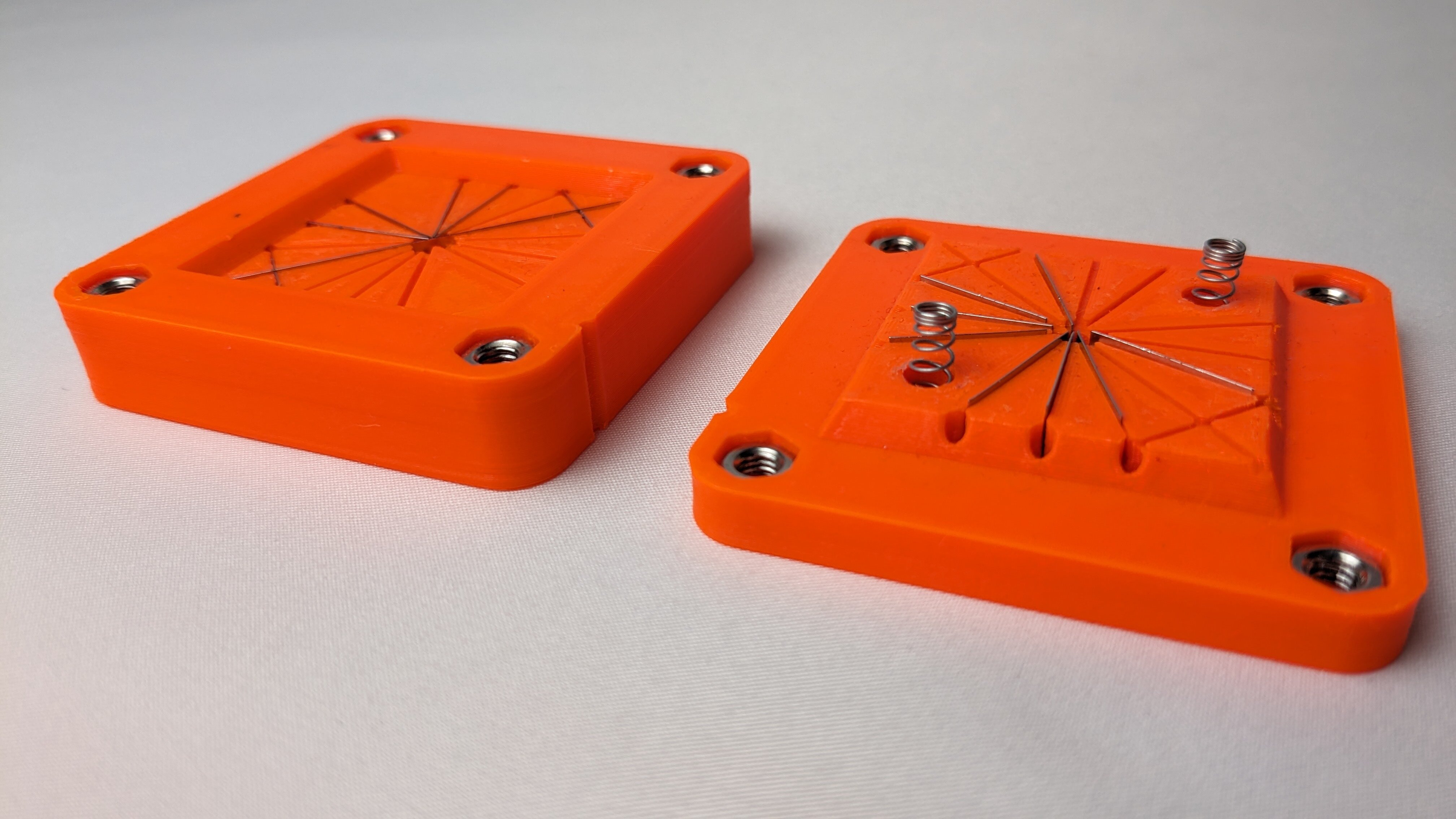
Of course there is more to this, like the springs you can see in the right die which keep the paper from sticking to it. It took many iterations until we reached a design which could reliably and accurately perform this operation. I hope we'll get to write another blog post about it soon.
But we grew confident that this process was viable and could actually be used to build the machine. So we started designing the whole thing, based on this simple idea.
Workstations - Creasing Press
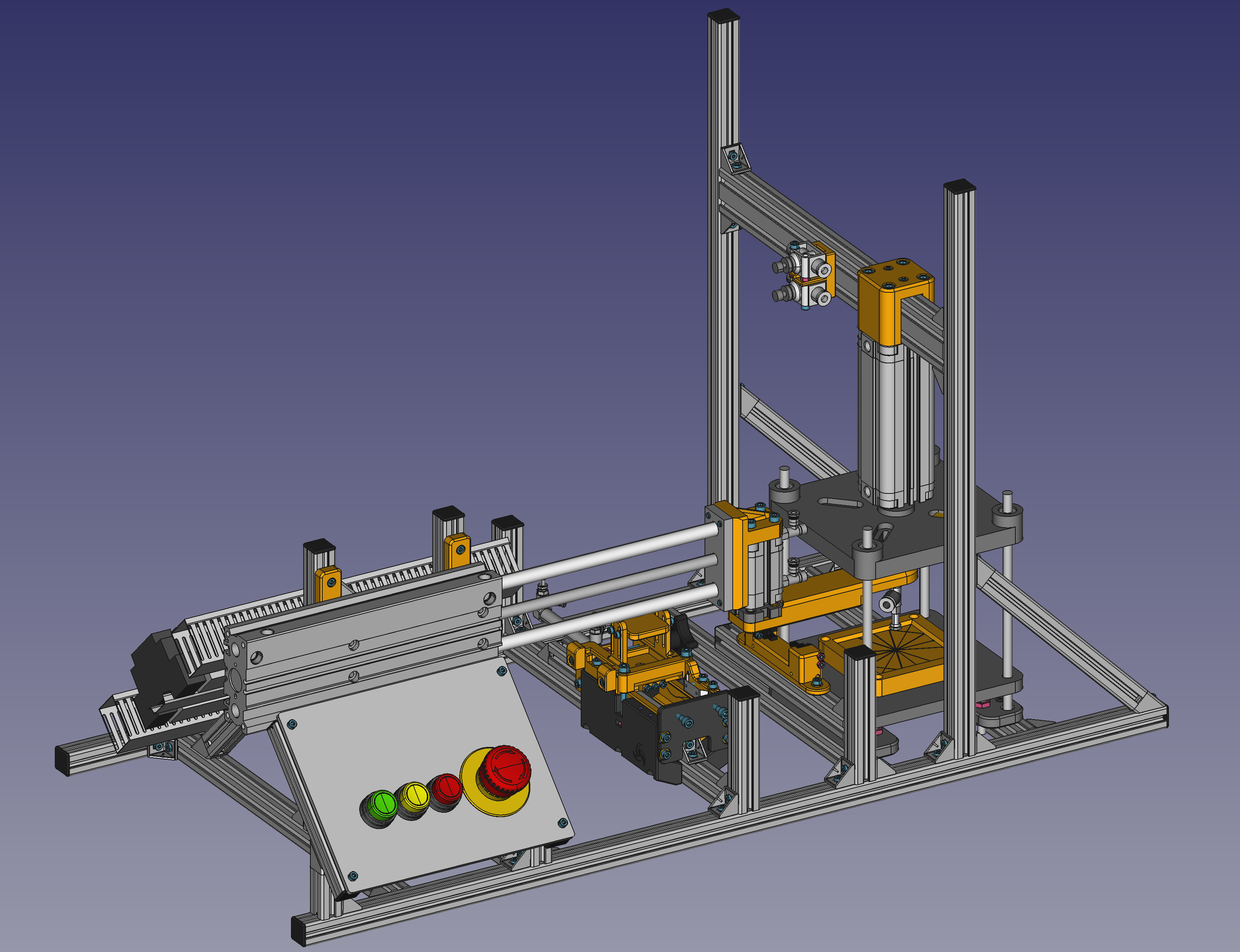
Alright, let's start dissecting the machine. The first component we will look at is the most important one: Workstations are the place in the machine where the actual transformation of raw materials into finished goods is taking place. Each workstation performs one step in the process of the production. Historically, workstations were operated manually. An operator would insert a part, perform the work, then remove the part, which could then be taken to the next station. In a more automated setting, the workstations can perform their tasks entirely automatically.
The tasks that can happen at these workstations are numerous. In the end, it always depends on the product to be produced. To get some ideas, take a look at Wikipedia's List of manufacturing processes...
In our case, only one workstation exists: The creasing press which creases the fold pattern into the paper squares. It is quite a simple workstation. It only has one movement axis - the pneumatic cylinder that moves the top half of the press down onto the paper and the bottom half. We used four precision rods to guide the two halves so they align precisely. And below the bottom half, there are hydraulic dampeners which smooth out the pressing motion to make it more gentle on the tools and paper.
Material/Part Handling
Having all the workstations in place is enough to start "production". But parts have to be moved from station to station manually which means the production still requires manual work. A key to a high degree of factory automation is reducing the need for humans here, in the Material handling or part handling. Material handling always answers the question "How can we move materials or parts from location A to B". A and B are usually in close proximity or at least part of the same factory complex. This includes everything from getting "raw" materials into the machine, moving products inside the machine, ejecting finished parts, or moving parts from one machine to the next.
For automating part handling, many different types of handling equipment exist. It comes in any scale imaginable, from nanometer-precise devices in the semiconductor industry to the largest cranes in the marine cargo world. For now, let's focus on the manufacturing industry. There, you'll typically see:
- Robotic arms, being the most well known and most versatile handling solution. These can do essentially any handling job that a human arm can do.
- "Pick and place" mechanisms, which are more fixed in their operation. They pick up a part in one location and then place it in another. Historically, such pick and place mechanisms were often implemented completely mechanically!
- Conveyors, moving materials over longer distances, but usually in bulk without keeping individual parts precisely aligned.
- Rotary tables, rotating parts from one station along their circumference to the next. Some station usually adds new parts to the table and another one ejects the finished ones.
- Rail or track systems, being a child of conveyors and rotary tables. They aren't confined to the circular path of the rotary table but instead can move parts to arbitrary locations. But in contrast to traditional conveyors, the rail carriages keep parts precisely aligned the whole time.
For us, with the flower machine, there were two handling questions:
- How do we move the fresh paper squares from the infeed into the creasing press?
- How do we move the creased papers from the creasing press to the output bin?
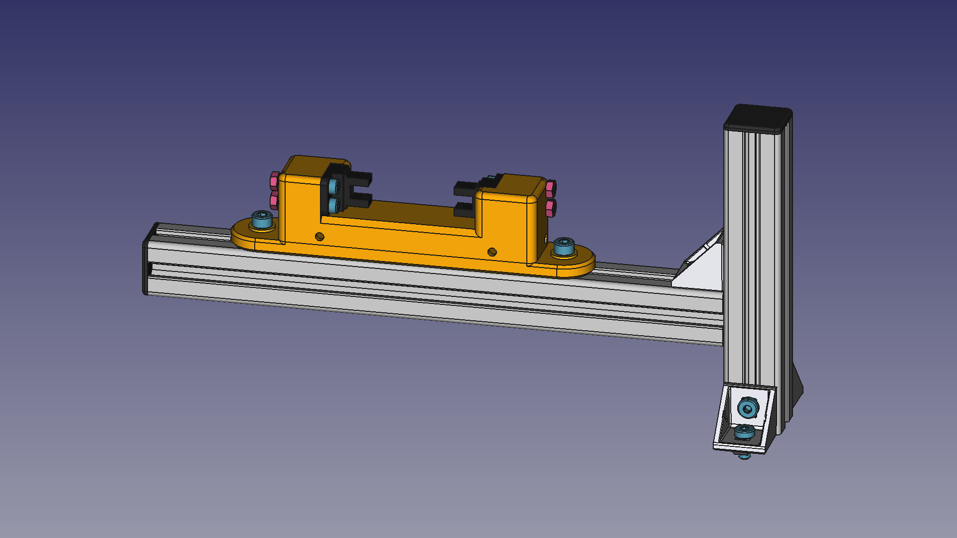
The answer we chose is a pneumatic pick and place design. We also chose to combine both handling tasks into one mechanism. This allowed us to keep the mechanical complexity of the machine a lot lower than it would have been otherwise. The trade off is increased cycle time and programming complexity.
This pick and place mechanism consists of two air cylinders, one for horizontal movement and one for vertical movement. As you can see, they perform an "up, forward, down; up, backward, down" motion. In one location, a paper is picked up and in the other, it is dropped again.
How is the paper actually picked up? Well, this is yet another facet of material handling... There are many, many different solutions, all tailored to different kinds of materials or parts. In this specific field, you will mostly see these two:
- Mechanical Grippers which grab the part like a human would, with two opposing "fingers".
- Vacuum suction cups which grab the part using suction.
As you can see, we chose to use a suction cup for the flower machine. Mechanical gripping of such delicate pieces of paper would be much more challenging, let alone finding a way to then accurately release the papers into the creasing press again. With the suction cup, this becomes very easy.
Finally, there is one more aspect of our design that I want to highlight: The pneumatic pick and place can only reach two positions. These are the end stops of the horizontal cylinder. But as we have combined two handling tasks, we need a third location as well. Otherwise we'd place the creased papers back into the infeed which would not make any sense. To get around this, we used a trick: A sensor detects the position of the horizontal cylinder along its retracting travel. Timed by this sensor, we disable the suction cup while moving, so the paper is dropped precisely into the output bin.
Part Feeding
Related to material handling is material feeding. It concerns itself with the task of bringing raw material from bulk storage into the machine. This is often more difficult than you would expect: The best ways to store material efficiently are often the worst for automated feeding. For example, take a box filled with loose screws. How would you automatically extract and orient them one by one? Clever feeding solutions try to solve these problems (and if you're curious about the screws, take a look at this video).
The choice of a feeding solution largely depends on three factors:
- What form is the material stored in?
- How does the material need to be presented to the following handling equipment?
- How much throughput does the feeder need to have? How many parts per minute need to be fed?
For the flower machine, we have the paper squares stored as a stack. Single pieces of paper should be presented, precisely aligned, for the pick and place to pick up and move to the creasing press. We went with a solution that is called a friction feeder. It makes use of friction to separate single pieces of paper from the stack. Making the paper feeder work reliably was probably one of the biggest challenges in this project. There is certainly going to be another blog post where we will explain the paper feeder in more detail. For now, here is a little (simplified) animation of the feeder in action:
Part Checking
With all things mentioned so far, it should theoretically be possible to build machines mass-producing absolutely everything. Except, in the real world, things often go wrong or don't behave exactly the same every time. Methods are needed to verify that produced parts meet all requirements and that the machine is working as it was designed to. This is called part checking and is an integral part of any automated production line. Of course this is closely related to QA (quality assurance) as well.
So, how can we automatically check parts and what should be checked, anyway? After all, there's so much that can be wrong with a part that it is hard to verify everything. Generally, part checking should focus on problems which are likely to occur with the chosen manufacturing process. You'll have to analyze your process and experiment a bit to find those likely problems. But you must do this before designing the part checking. It is not really possible to check for defects which you didn't anticipate during planning.
In our case, misalignment of the papers is the number one process failure so we needed a way to check that each paper is correctly positioned. The solution we chose was two light barriers at the left and right edge of the paper squares. This way we can detect when the paper shifts too much in either direction.
This sensor is placed such that it is passed both when moving a new paper into the press and when removing a creased paper to place it into the output bin. This way we can check in both situations whether the paper is correctly positioned and raise an alarm if it is not. So far, this setup has managed to catch pretty much all failures which happened.
In more serious machines, you'd see more checks being performed. Getting ever more popular, vision based part checking is a very nice solution. Pictures are taken of each part under controlled lighting and compared against known good (or bad) reference images. This can detect a very wide range of possible defects and thus is a powerful checking method.
Control
Finally, one thing no machine can do without is some form of control system. Commonly, this would be a PLC (Programmable Logic Controller) or DCS (Distributed Control System). Our "PLC" is the Poppy Logic Controller, a home-grown solution that I've written about previously. The controller's job is monitoring the process and sequencing control operations. In our case, it is mostly concerned with actuating the air cylinders and reading sensors to correctly time each movement and check for process abnormalities.
As the controller needs to be connected to all the sensors and actuators, also called field devices, a large amount of wiring is needed. Usually, this is hidden away inside a control panel, but in our case, we just mounted the electrical assembly directly to the back of the machine.
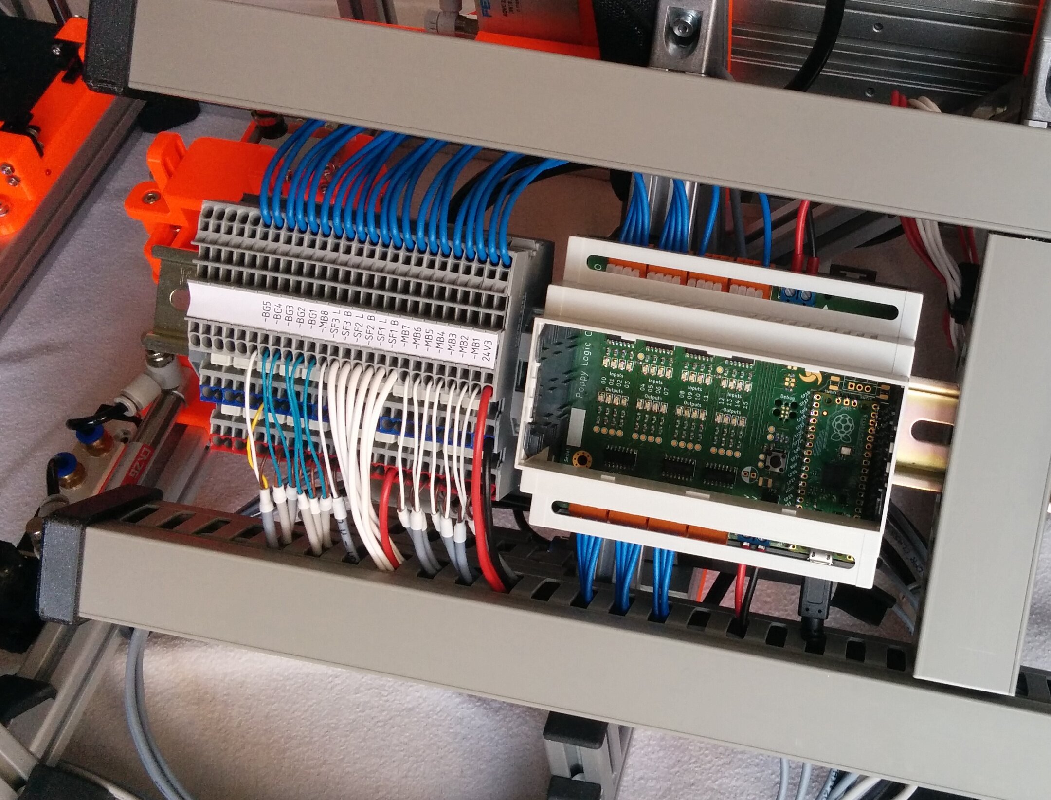
To the right, you can see the Poppy Logic Controller and left of it is a strip of terminal blocks. These are intermediate connectors between the PLC's inputs and outputs and the field devices. The blue wires at the top lead to the controller's I/O. The multi-conductor cables at the bottom lead to all the sensors, buttons, indicator lights, and pneumatic solenoid valves. Terminal blocks are essential for good wire management. They allow to keep the connections organized so it becomes easy to, for example, swap a broken sensor if that is ever needed.
Another part of the control system is the "user interface". By this, I mean the buttons used to start and stop the machine and the indicator lights which display the status.
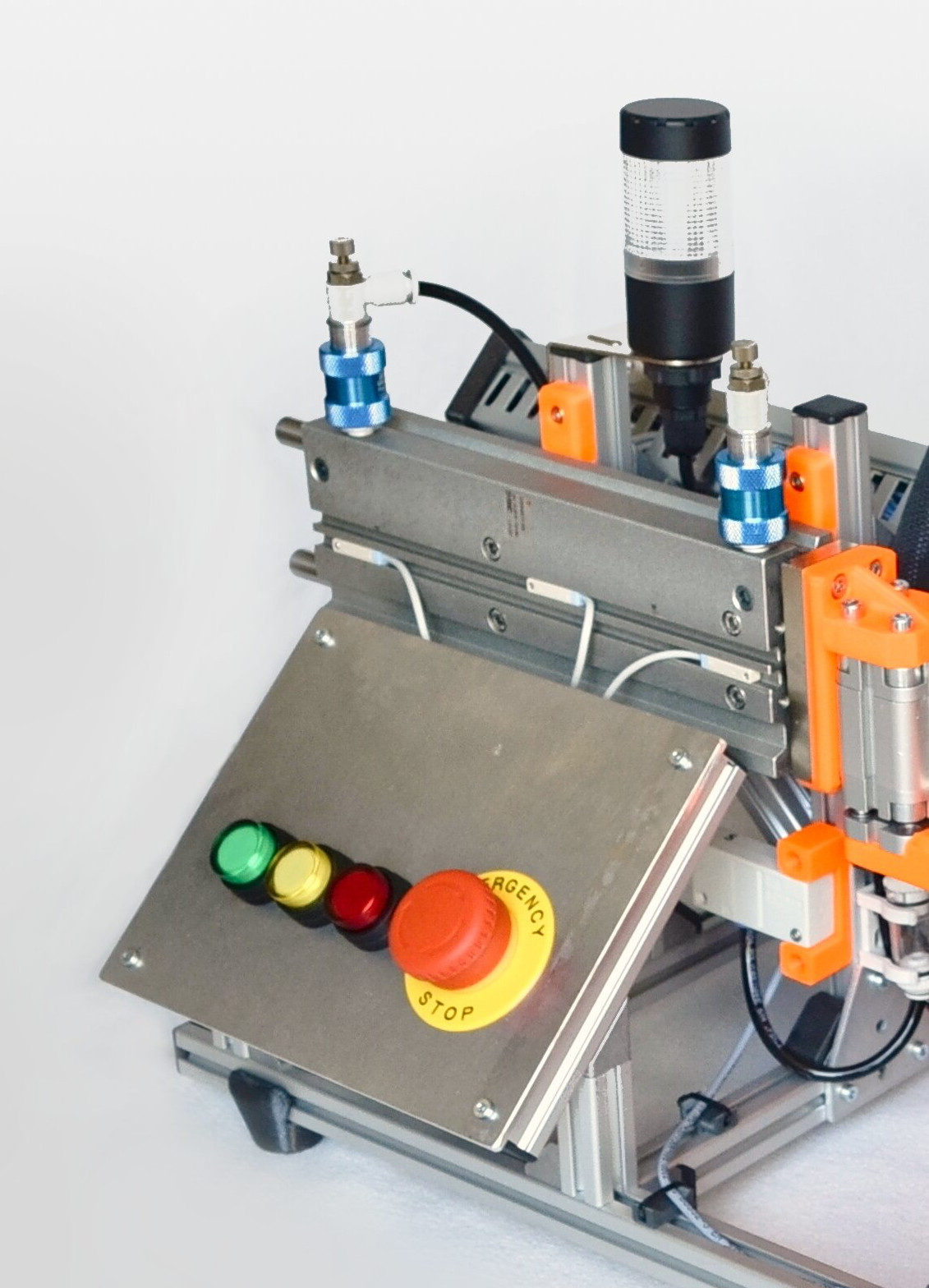
For the flower machine, the "UI" is super simple. There are three buttons for start, manual step, and stop. Manual step means running one sequence step and then waiting. This is useful for troubleshooting problems. Each button then has a light built in which displays the corresponding status: The green start button lights up while the machine is running, the yellow manual step button blinks when waiting for the button press to commence the next step, and the red stop button lights up while the machine is stopped and ready to start.
Beyond this, we have a small signal tower at the top. It blinks and beeps when a fault occurs to make the operator aware that something went wrong. There is, however, not really a way to find out what went wrong at the moment. A small display for status messages would be a nice addition in the future...
Finally, there is the big emergency stop (e-stop) button. It immediately cuts power to all actuators to stop the machine in an emergency. This completely bypasses the controller to ensure that a programming bug cannot interfere with this safety feature.
That's all for now. This was just an overview - we will hopefully write more about the individual topics in the future. For now, if you haven't already, why not read a bit about Pneumatics? :) Or head to the overview of all flower-machine posts.