In 2023, I built a machine called the "CNC Adhesive Applicator", to automate the process of attaching a display to a custom PCB using adhesives. In typical fashion, I only get to writing about it now. But better late than never! So here is a blog post about all the details.
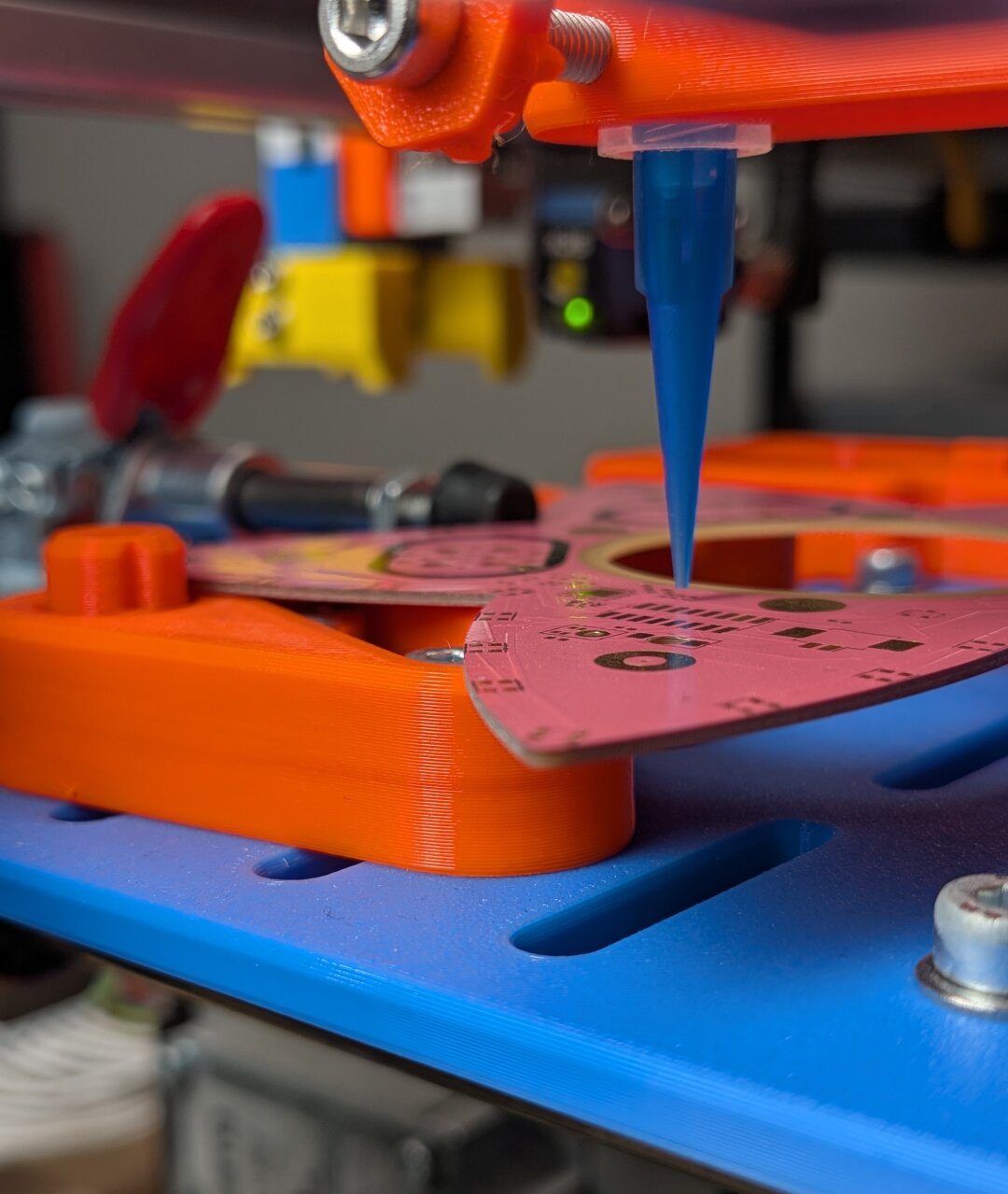
Video
Before diving in, let's start with the showcase because I know that is all you readers want — here is a video of the CNC Adhesive Applicator in action :)
The Idea
I guess the most important question to answer is about the origins of the idea and the purpose of the machine. To explain, I have to introduce another project first, which is closely tied to this machine: The "flow3r badge", a music synthesizer that was developed for the 2023 Chaos Communication Camp. You can learn more about it on the website (flow3r.garden) or from the camp talk about the project ("How to grow a flow3r" on media.ccc.de).

The flow3r badge was an open-hardware project for the CCCamp 2023.
The only thing you need to know about flow3r for this blog post is that it has a circular display that is sitting in a cutout of the front pink PCB. And during the design of the badge, we identified the challenge of attaching this display to the PCB.
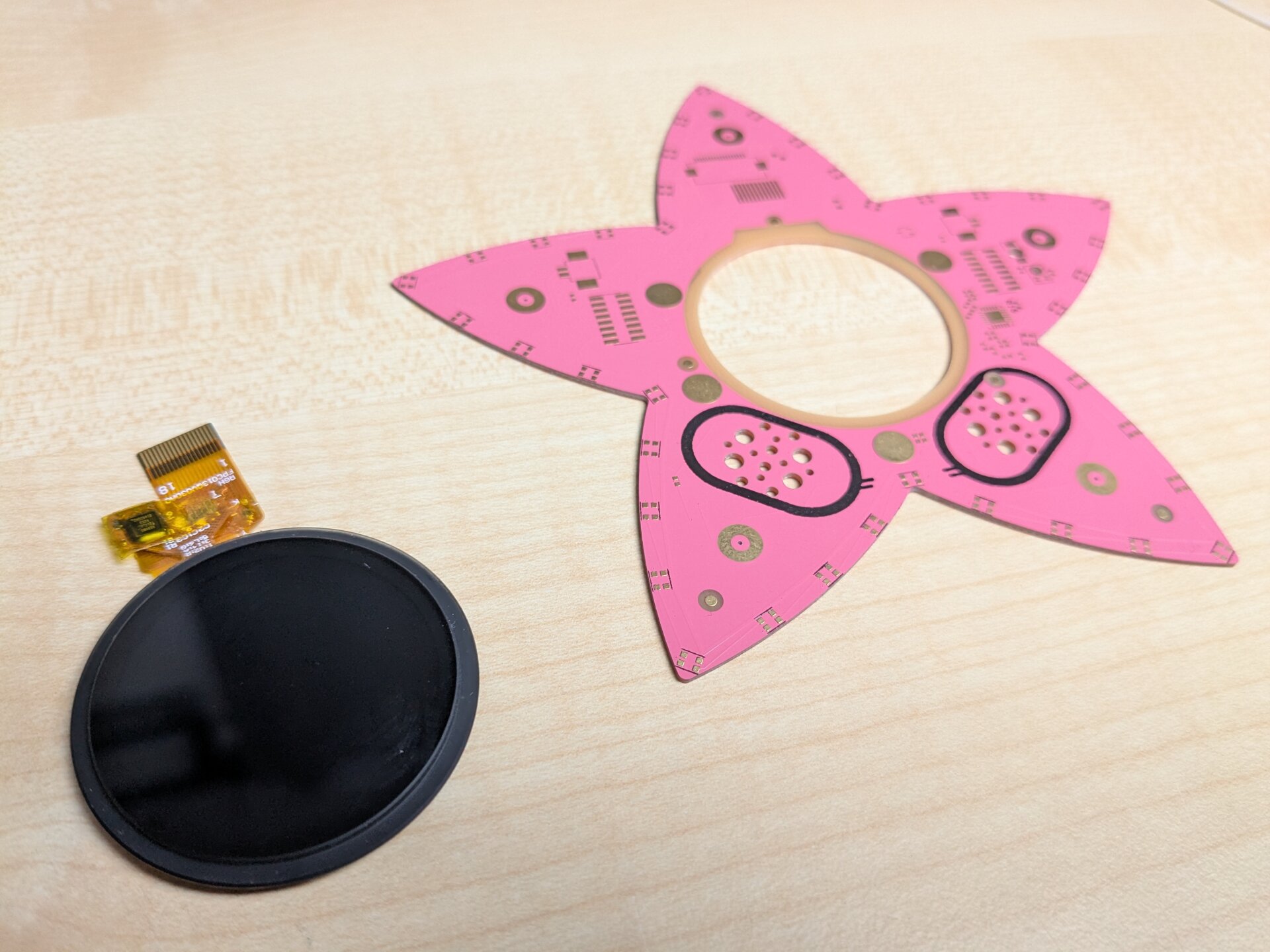
An (unpopulated) PCB and the display that needs to be attached. You can see the glass bezel on the display which is used for the adhesive.
While evaluating options, it became clear that we would have to use adhesives of some kind. As most adhesives come in liquid form, the assembly process would mean we would have to first apply a layer of adhesive to the PCB and then carefully place the display into it.
And this is where this machine was born: We were not entirely set on using a liquid-form adhesive, but the challenge of building a machine to automate this process, especially within the short timeframe of the project, intrigued me. It was clear from the beginning that this would be a risky adventure, but one that a great many things can be learned from. Even knowing that this might be a dead end, I wanted to use the flow3r badge as an excuse for dabbling more in manufacturing automation.
Excited? Well, I have to get something said before going further: While the "CNC Adhesive Applicator" got into working order, we unfortunately could not make use of it for the flow3r badge in the end. The main problem was that the logistics of the badge components prevented us from receiving everything in time to run this final assembly step on our end. We had to find a different solution on short notice, which ended up being little cutouts of sticky tape. Anticlimactic, I know.
Nonetheless, the machine exists and many many lessons were learned from building it. Let's take a closer look now.
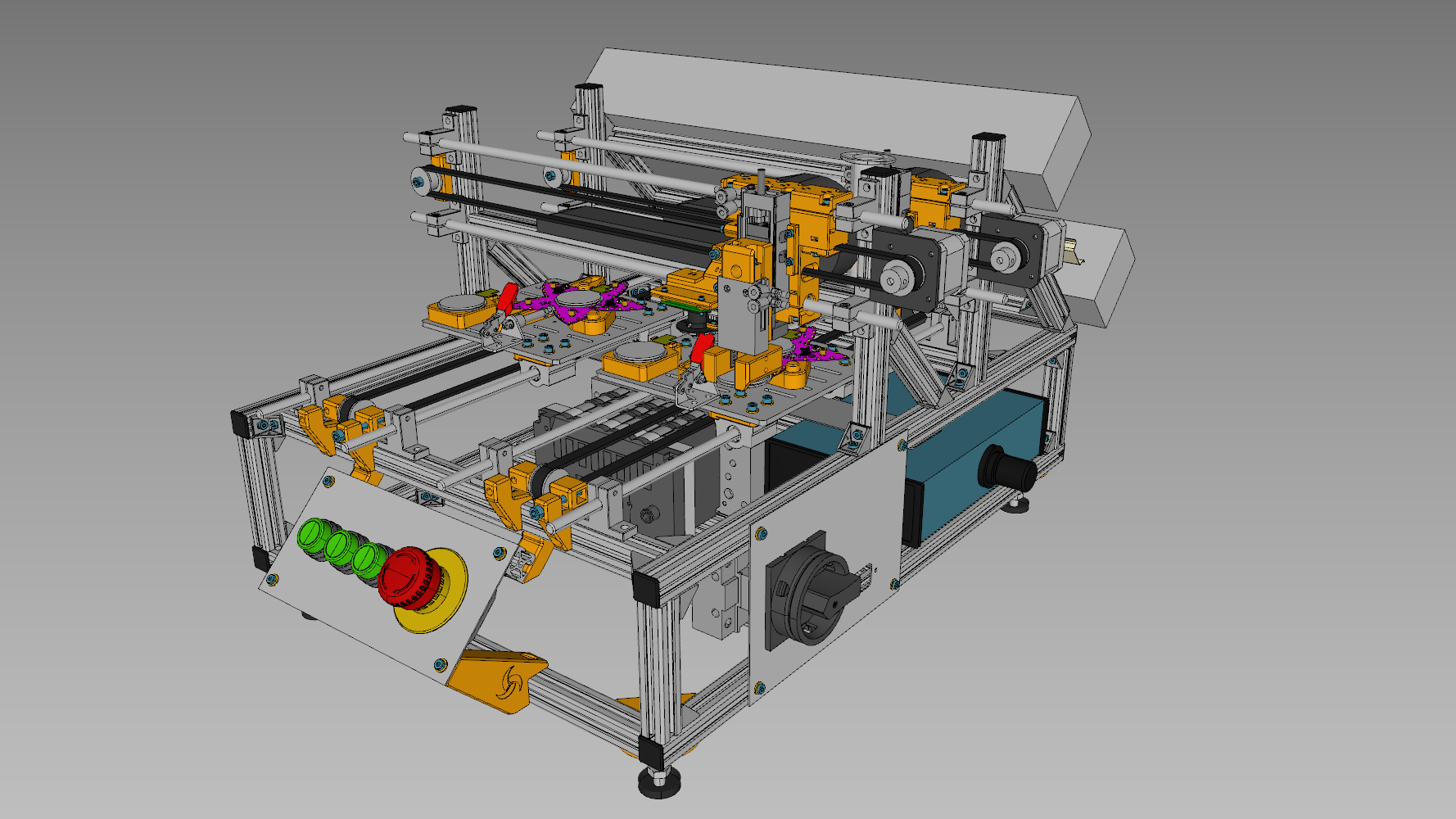
To give you a rough feeling for the the machine, here is a screenshot of the CAD model.
System Architecture
The first step in designing a machine like this is creating a functional system architecture that accounts for all the functions that the machine needs to perform. From this architecture, the mechanical and electrical design can then be derived. The more details you cover in the system architecture, the less risk there is to run into problems later.
When writing or drawing the system architecture documentation, it is a great idea to give each function an identifier so you can later track it across documents. I am going to prefix my identifiers with an = to mark functions.
For the CNC Adhesive Applicator, there are two main functions:
- =H1 Dispensing a pattern of an adhesive
- =H2 Placing the display precisely onto the PCB
Accompanying this, several auxiliary functions are required:
- =W1 Infeed and egress of process materials (The PCB and the display)
- =G1 Power supply (electrical and pneumatic in this case)
- =K1 Control system
- =B1 Detection of process problems
- =S1 Operator interfaces (buttons, indicators, HMI)
- =F1 Safety functions
Now that we have a rough overview, let's get more detailed; one function at a time.
=H1 Dispensing a pattern of an adhesive
To realize a function of the machine design, the first stage is research. Find ways that are commonly used to perform a particular task. As the first step, go as broad as you can. Then, converge on a realistic solution for your project.
For dispensing adhesive, a cheap and common solution is pneumatic dispensing. Air pressure is applied to the back of an adhesive cartridge which pushes the material through a needle. The flow rate can be adjusted by varying the needle diameter and air pressure.
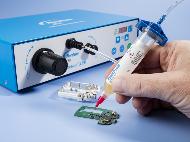
A manual pneumatic adhesive dispenser by Nordson EFD. Often, such dispensers are operated using a foot pedal.
Pneumatic dispensing can also be automated quite easily, by simply mounting the cartridge to a motion system. Depending on the application, the motion system can get as complex as a full 6-axis robot arm. Luckily, for this project, we can make do with a much more simple cartesian portal. Such portals can even be bought off the shelf:
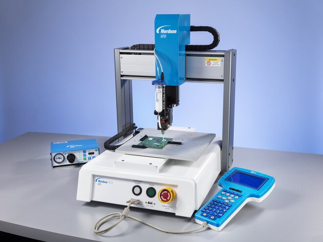
A cartesian adhesive dispensing robot by Nordson EFD.
For the CNC Adhesive Applicator, I chose a similar design. The PCB moves on one axis while the dispenser cartridge moves on a gantry along the other axis. To move the needle to the correct dispensing height, a pneumatic cylinder can move it up and down.
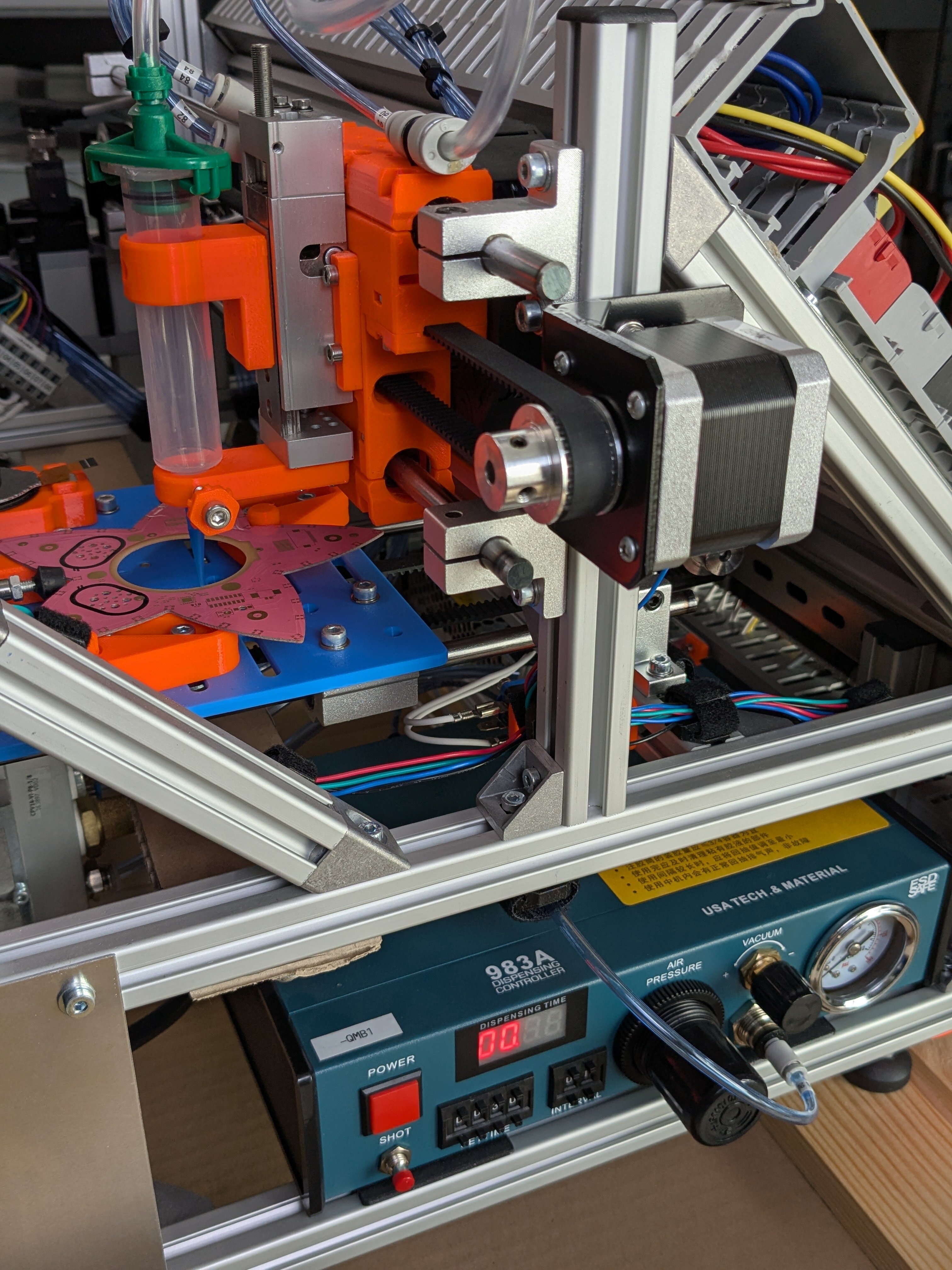
Dispenser gantry on the CNC Adhesive Applicator. Top left, the (empty) dispensing cartridge with a blue needle can be seen. At the bottom, the dispensing controller is visible.
I opted to use an off-the-shelf controller for dispensing, mainly because it already contains the required valves and pressure reducer in one neat package.
Getting a first system set up to run dispensing tests was rather easy — mastering the process to get reliable results was a very different story. You always have to keep in mind that there are a lot of parameters that need to be controlled. Just to name a few:
- Distance between needle and surface
- Manufacturing tolerances of dispensing needles
- Mechanical play of the gantry axis
- Different viscosities of different adhesives and temperature-dependency
- Pressure dynamics in the moment of switching on the dispensing valve
- Adhesive dripping from the needle while not dispensing
- Thixotropic properties of the adhesive
- Different behavior of different cartridge sizes
Unless you already know the ins and outs of a process, plan ahead that you will need to tweak parameters a lot. Design for exchanging components, by keeping things modular. Add elements to adjust known parameters and keep in mind that you may not even know all the important parameters yet.
Most importantly: Prepare yourself to take reliable and quantifiable measurements of the result so you can iteratively improve the process. And don't forget to document all the changes you make!
=H2 Placing the display precisely onto the PCB
The next task is to precisely place the display onto the PCB. The process of picking up a part and then placing it somewhere else is called pick-and-place in automation. This is a very common task, done with parts ranging from less than a millimeter in size up to multiple meters.
Every pick-and-place system is made up of the same two fundamental components:
- A handling system to attach to the part in question. Usually either by mechanical gripping or by vacuum suction.
- A motion system to move the handling system from the pick location to the place location.
Starting in reverse order, the motion system for the pick-and-place on the CNC Adhesive Applicator is the same as the motion system for the dispensing unit. This allowed reusing the same axis for motion of the PCB and reusing a lot of the design for the gantry axis. There is also another pneumatic cylinder taking care of Z-axis movement again.
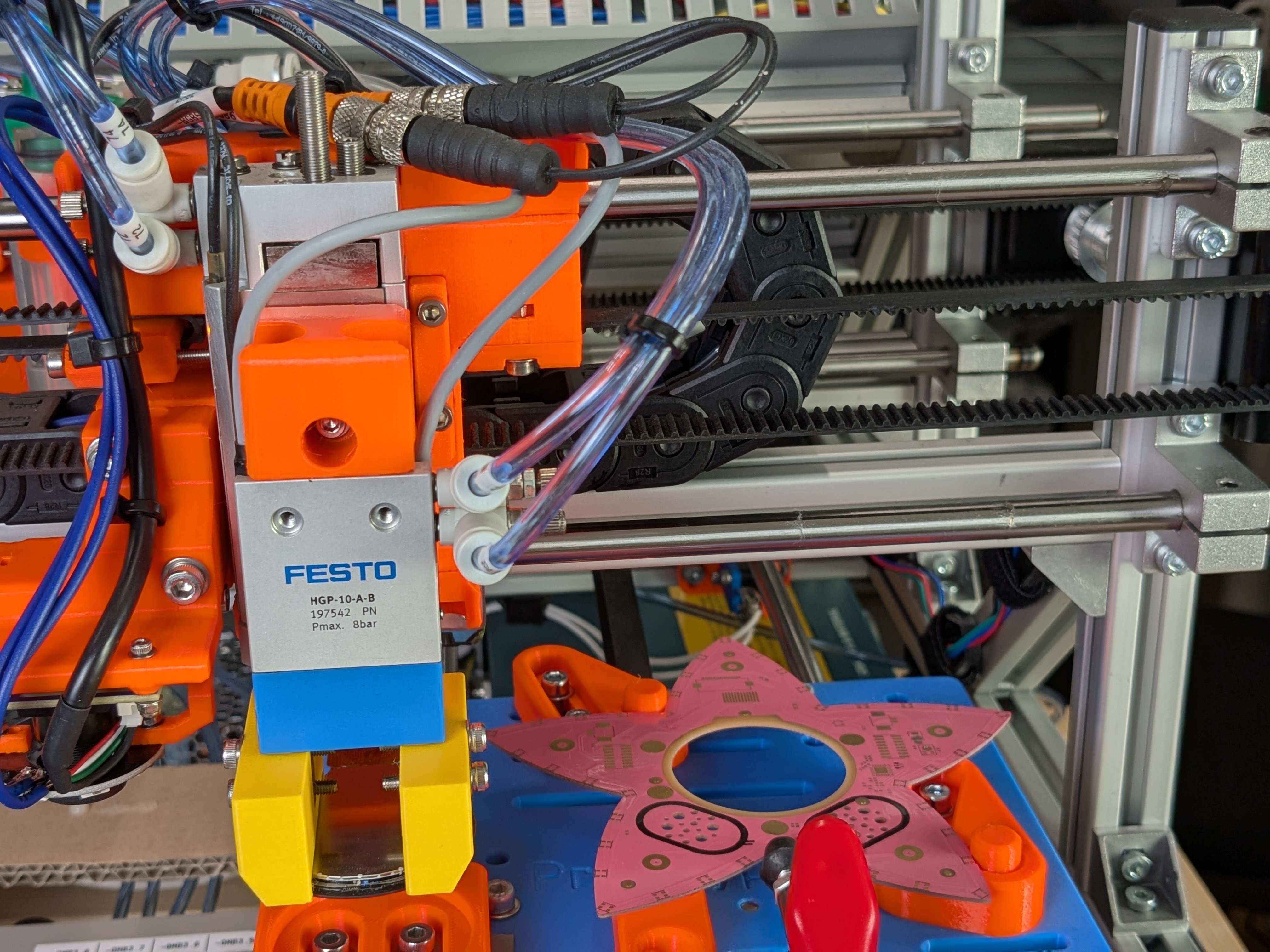
The pick-and-place gantry after just picking up a display.
The handling system was implemented as a mechanical gripper — a pneumatic gripper to be precise. Mechanical gripping has some advantages over vacuum suction for this use case, as I will show later.
With grippers, there are two design approaches:
- Form-locking, where a part is constrained simply by the geometry of the gripper fingers
- and Force-locking, where a part is constrained by friction force applied between surfaces of the part and the gripper fingers
In general, form-locking gripping should be preferred because it can be much better controlled than force-locking. Some big manufacturing companies go as far as requiring form-locking for all automated handling systems. Unfortunately, some parts, especially those not optimized for automated assembly, do not have the necessary geometric features to allow form-locking.
This is also the case with the display for the flow3r badge (such components are usually picked by vacuum suction). So I ended up going with a force-locking design. As expected, this proved to be quite challenging to get right.
So why the hassle? Well, a big part was that vacuum suction traditionally uses up quite a lot of compressed air (yes, the vacuum is created using pressurized air!). Also, as we had already explored this concept on the Flower Machine, I wanted to try my luck with mechanical gripping this time.
This choice comes with one additional advantage over vacuum suction: A mechanical gripper can be designed to self-center the part while gripping it. This is very nice when precise placement is required but the part is not precisely located in the pick location. Self-centering is achieved by two v-shaped fingers that nudge the part towards their common center point while the gripper is closing.
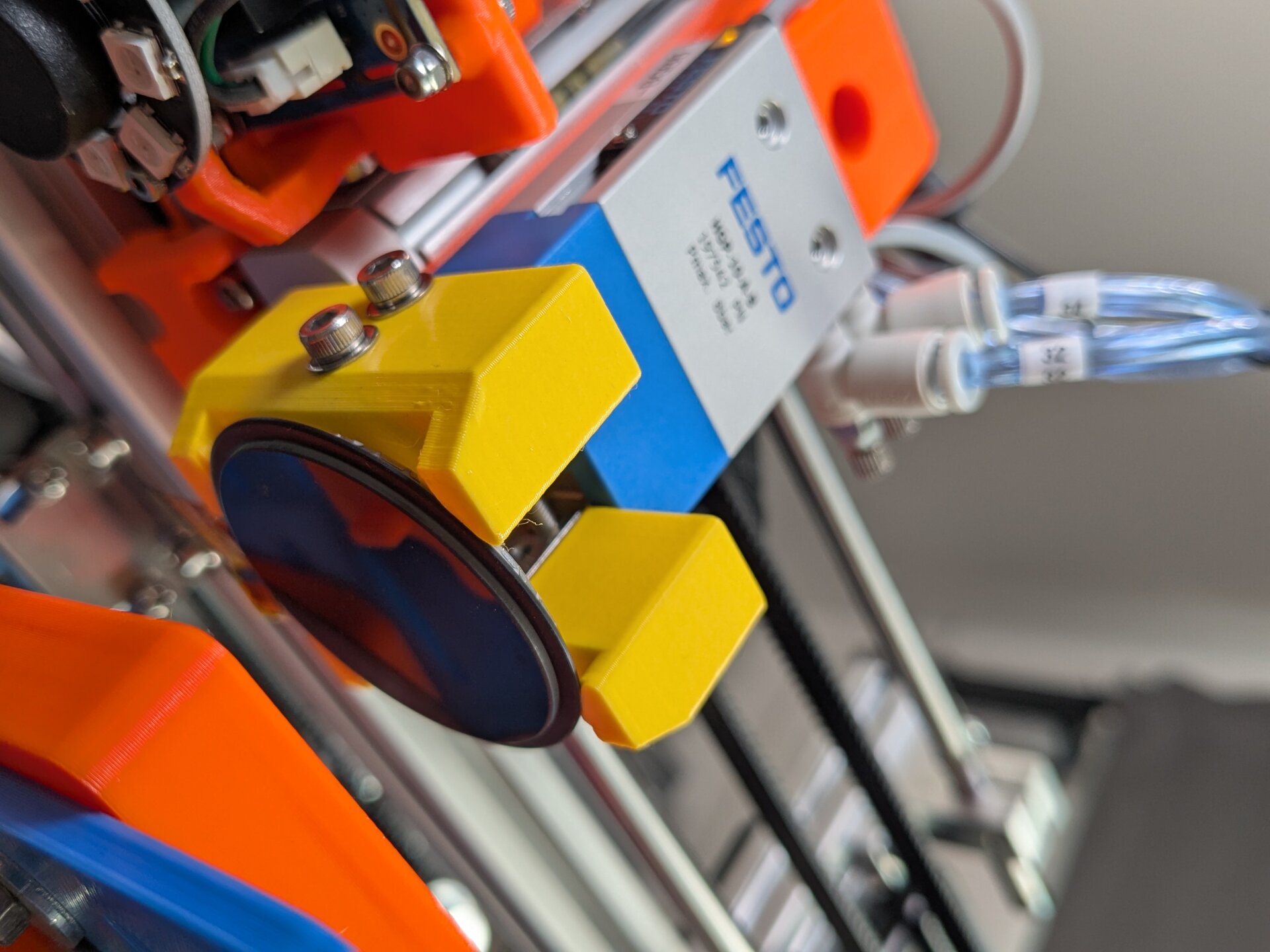
The gripper fingers holding a display. You can make out the angled contact surfaces that form the V-shape of each finger.
The tolerances here were quite tight because of the very slim bezel on the display. But once the gripper was adjusted to actually pick the display, it was surprisingly reliable. Calipers and a bit of calibration software made the adjustment process a breeze.
=W1 Infeed and egress of process materials
A surprisingly big part of automated manufacturing equipment is the handling of part infeed. In fact, a lot of processes are not fully automated, simply because a human is still needed for feeding parts. Automated feeding only starts making sense when very high part counts are processed. And even then, it is quite involved and requires a lot of care.
For the CNC adhesive applicator, it was clear that fully automated part feeding would not make sense. So I chose a half-automated process where an operator places parts into fixtures and later manually removes the finished product again.
The concept is a "sled" that moves to the front for loading, then acts as one of the motion axes for the two processing steps, and later moves back to the front for unloading.
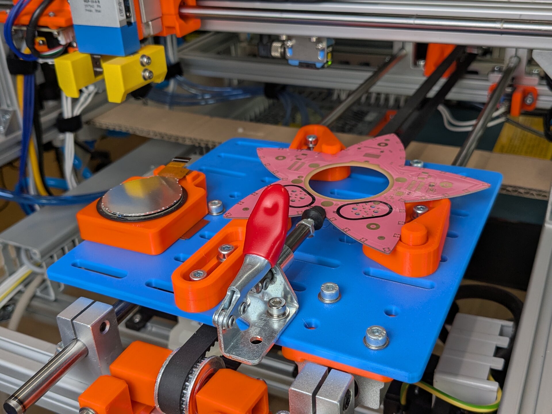
The sled holding the display and PCB.
The machine was actually designed for two such sleds, so one can be loaded while the other one is processed. This would have allowed 100% machine operation time, or "OEE" (overall equipment effectiveness) as the industry calls it. The second sled was never actually physically implemented, though.
On the sled, two fixtures are mounted: One for the PCB and one for the display. The display simply sits loosely in a nest with two protrusions keeping the display connector aligned. It is later precisely located by the self-centering gripper mechanism.
The PCB, on the other hand, needs to be in a precise location. As such, its holding fixture is designed to clamp it into precise alignment using a toggle clamp.
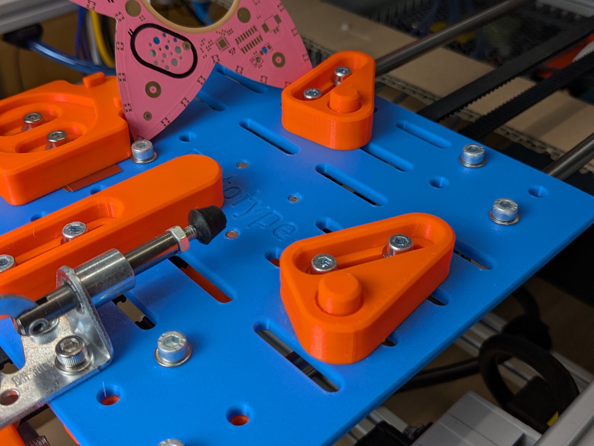
6-point fixture for holding the PCB in a precise location. In the top left, the nest for the display is also visible.
To design fixtures like this one, where the precise location of the part is critical, an often-used approach is the 3-2-1 method. This is a method where 6 locating features are used to constrain the 12 degrees of freedom of a part exactly and without any over-constraints. It is an amazingly simple, but powerful design tool, so if you are interested, I want to recommend reading this great explanation here: Guide To Locating & Clamping Principles
One caveat is that locating accuracy relies on the accuracy of the part's dimensions. I feared that the machining of the PCB edge may not be accurate enough, so as a fallback we prepared an additional measure: A vision system that detects precise patterns (fiducials) on the PCB and then corrects for the deviation in software. More on that will follow below, but luckily the mechanical precision was high enough to not cause any problems anyway.
=K1 Control system
With all the mechanicals taken care of, the next critical component is the control system tying it all together. This is not only about the software, but all the electrical hardware that is making the system run.
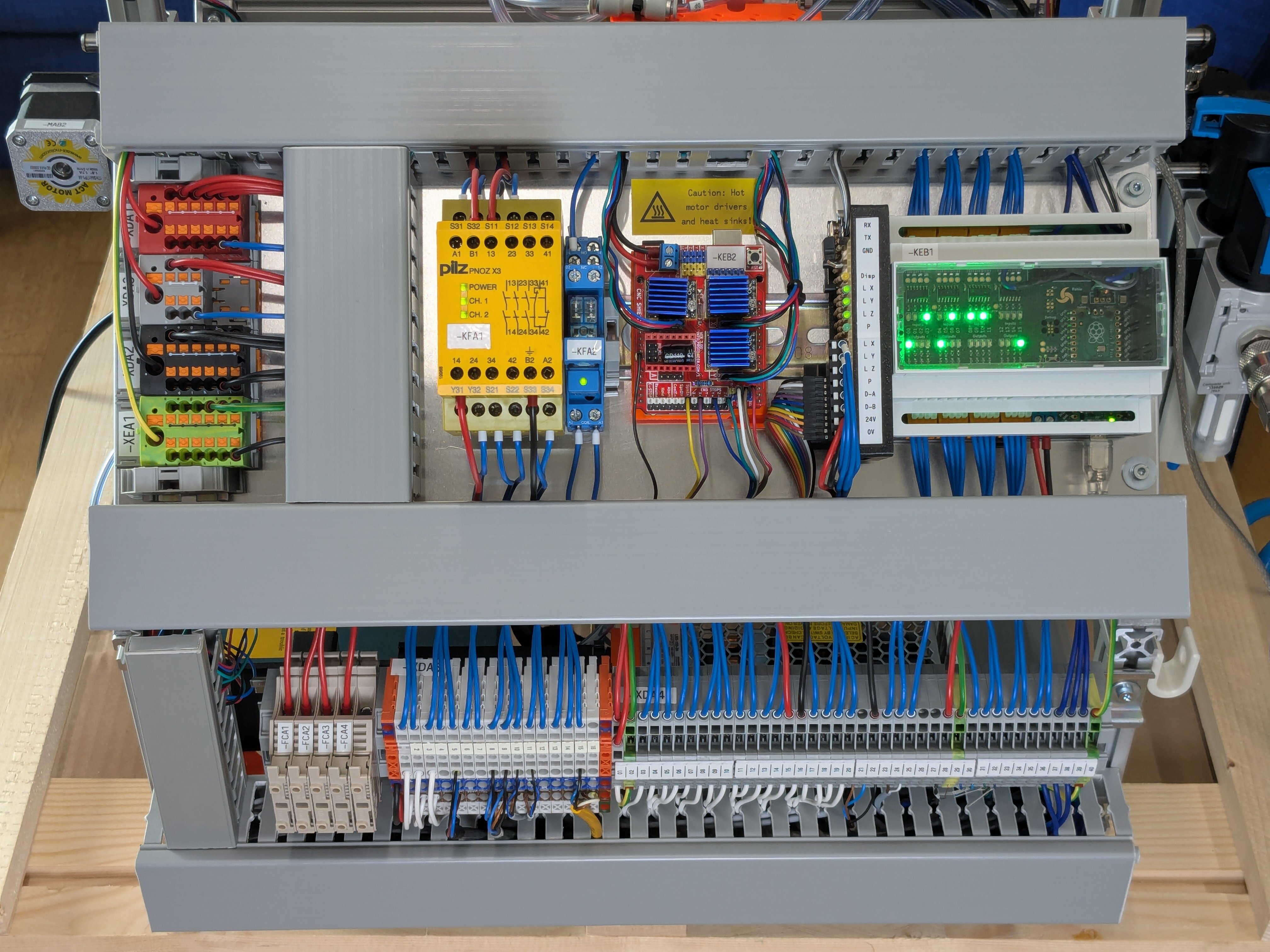
The control panel on the back of the machine houses all the electrical equipment to make the CNC Adhesive Applicator run.
The brain of the operation is once again my Poppy Logic Controller. But as this project also has motion control requirements, a second controller sits beside it — an Arduino with a CNC shield is being used to drive the stepper motors. It is running GRBL and receives commands from the Poppy Controller for performing movements. The communication between the two is a plain UART, nothing fancy here.
Besides these controllers, there is a big yellow part. That is a safety relay, used here to implement the required emergency stop function. More about safety will follow in the next section.
Finally, you can see a large number of terminal blocks in the bottom of the picture. They simply connect signals from the control system to signals from the various sensors and actuators. Having an intermediate connection point like this proves to be very useful. It keeps the wiring a lot cleaner, and changes on the machine become much easier to implement. Troubleshooting problems is also a lot more fun when you can temporarily switch up the wiring without much effort.
Talking about troubleshooting, one thing you shouldn't ever miss is proper
documentation of the wiring. If you are curious, I have made the wiring
diagrams for this machine available for download:
CNC-Adhesive-Applicator-Wiring.pdf
I used QElectroTech for making these drawings. It is not as comfortable as the proprietary equivalent, but certainly works well enough to do the job.
Pneumatics
Beyond the electrical parts, the control system also has some pneumatic components. As I mentioned earlier, air cylinders are used for up and down movement and the pick-and-place gripper is also a pneumatic variant.
To control movement of these air cylinders, a pneumatic valve terminal translates the electrical signals from the controller into pressurized air for the respective chambers of each cylinder.
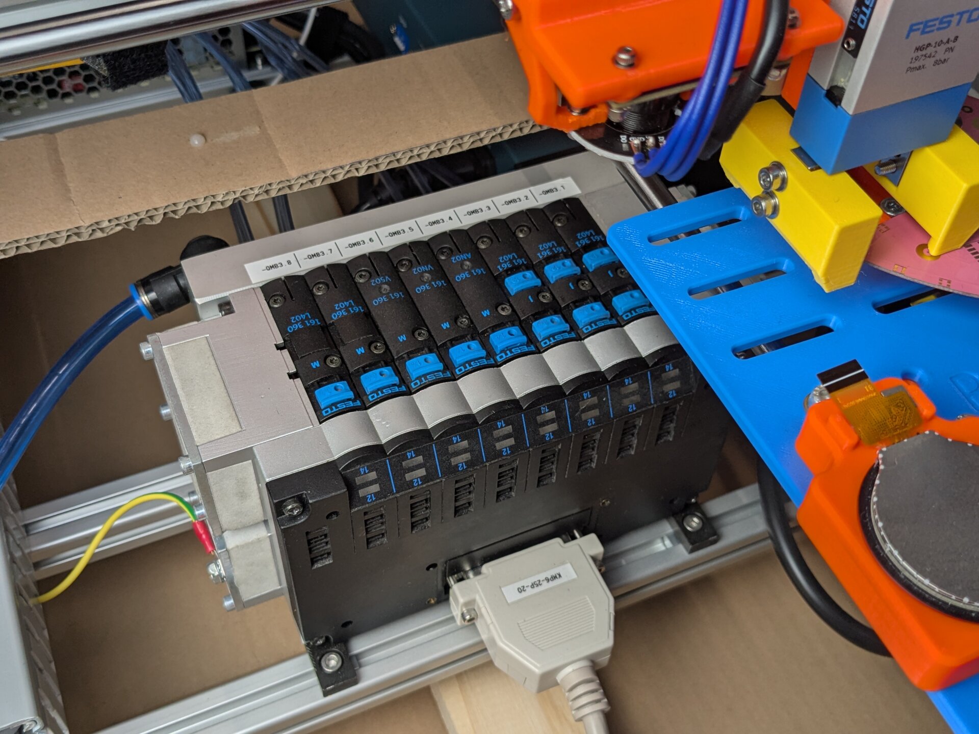
Tucked away beneath the functional area of the machine is a valve terminal that controls all the pneumatic actuators.
For feedback, the pneumatic actuators are each equipped with magnetic sensors. They signal to the control system when a cylinder has reached its target position.
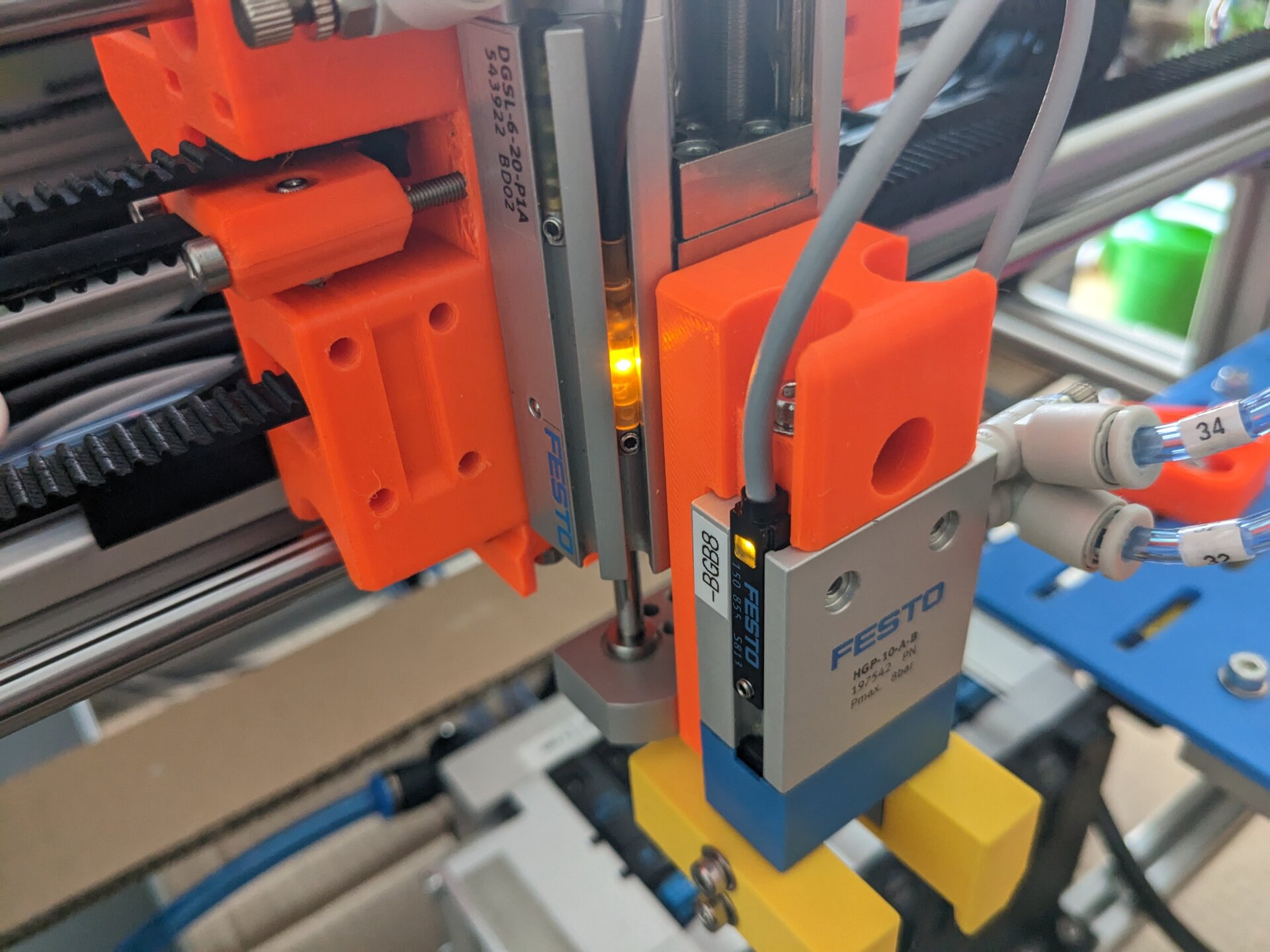
Sensors are fitted into slots on each air cylinder. They detect the position of the piston magnetically.
I won't go into details about pneumatic systems here, but you can find out more in an earlier blog post of mine about the topic: Pneumatics — Rahix' Blog
Software
The Poppy Logic Controllers was programmed in MicroPython this time, mostly due to time constraints. The software design borrows ideas from PackML and the associated ISA-88 standard. For communication, a MODBUS ASCII interface is available via USB serial. That interface is used by the web HMI which I will get back to in a minute.
As mentioned, communication with the GRBL motion controller happens over a UART interface. The Poppy Controller sends G-Code commands to initiate motion. GRBL then does open-loop control of the stepper motors and reports back to the Poppy Controller when motion jobs have been completed.
So far I haven't gotten around to publishing the software for this machine — most of it is not really reusable. But if there is interest, I am certainly open to sharing the code.
PackML State Machine
The main software design concept taken from PackML is the state machine. PackML defines what states a machine can be in and how transitions between these states are possible. The model is designed for any kind of automated manufacturing equipment, so it naturally applies well to the CNC Adhesive Applicator.
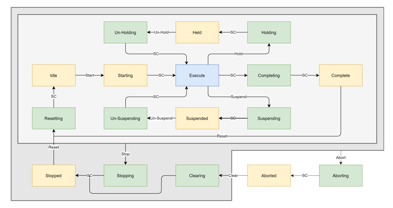
PackML states and transitions. SC is short for "state complete".
Timmerdebim, CC BY-SA 4.0, via Wikimedia Commons
A machine always starts in the Stopped state. It has to be reset before being ready for operation. Once ready (Idle), it can be started and then produces its product in the Execute state until it either completes (for batch production) or is taken out of the Execute state by another transition.
Of note is the difference between the Held and Suspended paths: By definition a machine is Held when a production stop is directly requested by the operator. It is Suspended when it is waiting for further materials to process. This distinction is very useful so production monitoring can easily tell how much a machine is blocked by an upstream or downstream bottle-neck (Suspended) or by the operator needing to pause the process (Held).
A fun little exercise is taking a common machine that you often interact with and trying to map its behavior into this state machine. For example a 3d-printer or some appliance like a washing machine.
PackML Modularization
Another nice aspect of PackML/ISA-88 is that the state machine can be used to modularize the software for a machine. Each independent subsystem becomes an "equipment module" which bi-directionally interacts with the PackML state machine of the entire "unit". This makes for a clean application architecture that is easy to extend and debug.
For the CNC Adhesive Applicator, 4 equipment modules were defined:
- Dispenser (=H1)
- Gripper (=H2)
- Sled (=W1)
- Misc (an equipment module to take care of motion control initialization and other small tasks)
The direct mapping to the functional subsystems of the machine is of course not by accident.
=F1 Safety functions
Closely related to the control system is the safety of the machine in general. Because we were going to use the CNC Adhesive Applicator for some proper work, I of course wanted to make sure it followed all the industry-standard practices for ensuring machine safety.
In the EU, this means adhering to the machinery directive (2006/42/EG, Wikipedia). This is done by performing a risk assessment, guided by the ISO 12100 standard. This is a big topic that I will need to cover in more depth another time. In broad strokes, that in no way do the topic justice, I do want to go over some very important points, though:
- When a hazard is identified, reduction should always be attempted in this order:
- Preferredly, by design changes that eliminate the risk inherently. For example, by eliminating a pinch point, or by adding an enclosure that prevents access to the hazard.
- If such design changes are not possible, by implementing technical means (safety functions). This could be safely limiting movement speeds or the addition of safety sensors, for example.
- Only if neither 1 or 2 are reasonably possible, is a risk mitigation by organizational means allowed. So the addition of warning labels or operating guidelines.
- Safety functions must be reliable. In the industry, ISO 13849 gives detailed instructions for determining the degree of reliability. It is never ever good enough to implement them in plain software logic. Hardwire your safety and use components that you can trust.
- An emergency-stop button is not a (primary) safety function. Its sole purpose is to provide a reliable means of emergency control for situations not foreseen by your risk assessment.
- A risk assessment is nothing to be feared. Apart from the legal requirement, you should view it as a tool that helps you sleep at night, knowing you haven't forgotten anything dangerous. Once you get into the methodical approach of hazard identification and risk assessment, it is actually not that difficult at all. Go do it, even for your own sake!
For the CNC Adhesive Applicator, the risks were fortunately quite manageable, so no overly complex safety functions needed to be implemented. The only notable component is the e-stop circuit which I intentionally overdesigned to play with a high-reliability implementation a bit. Yes, the e-stop is considered a secondary safety function after all, but as mentioned, it must not be used to mitigate any identified risks.
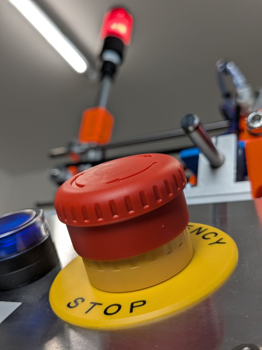
No machine may miss this: An emergency stop button
The e-stop of this machine is built as a two-channel system performing up to PLe (electrically, STO) and PLc (pneumatics, SDE). Those are ISO 13849-specific terms. For now, it is enough to know that no single fault in the safety system could lead to a loss of safety at any time. STO stands for safe torque off which means as much as immediately cutting all power to torque-generating parts (motors) of the machine. SDE means safe de-energize which is the equivalent for pneumatics — safely releasing all air that enacts a force on any of the pneumatic actuators.
The high-reliability design is achieved by redundant e-stop contacts and a very smart safety relay (PNOZ X3) that detects all kinds of unsafe faults and safely enacts each of the mentioned mechanisms for stopping the machine.
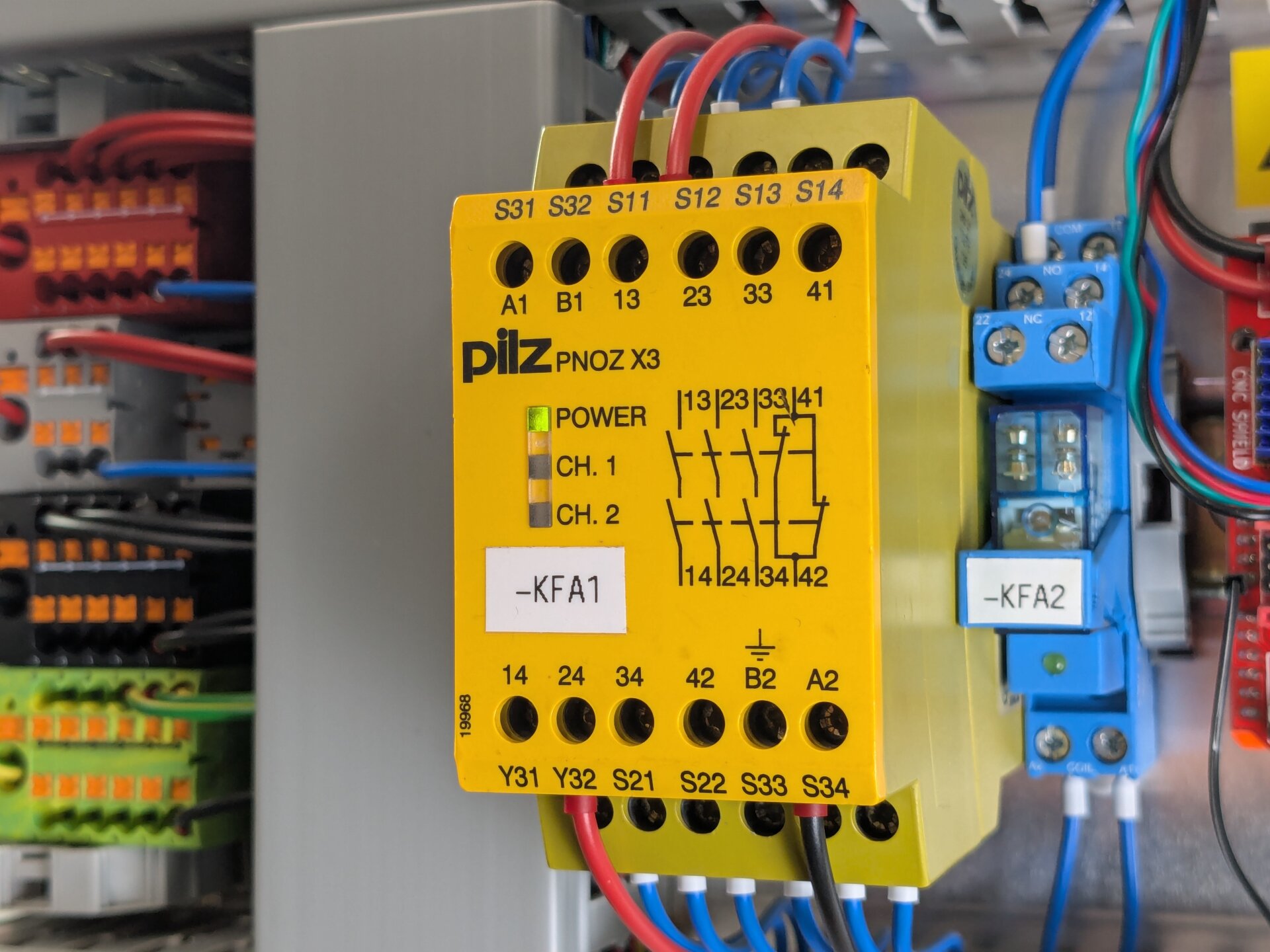
This is the PNOZ X3 safety relay that is used for the emergency stop.
It also fulfills yet another safety function: The relay is interlocked with the reset button such that unexpected startup of the machine is prevented in all situations.
=S1 Operator interfaces (buttons, indicators, HMI)
Talking about that, the reset button is of course not the only button on this machine. There are more operator interfaces — controls to instruct the machine what to do and indicators to report back the state of the system.
The CNC Adhesive Applicator has a number of hardware and software operator interfaces:
- 4 (illuminated) hardware buttons for cycle start, reset, and emergency stop
- a stack light with an alarm buzzer, as a global status display
- a web-based HMI for maintenance, commissioning, and troubleshooting
Hardware Buttons
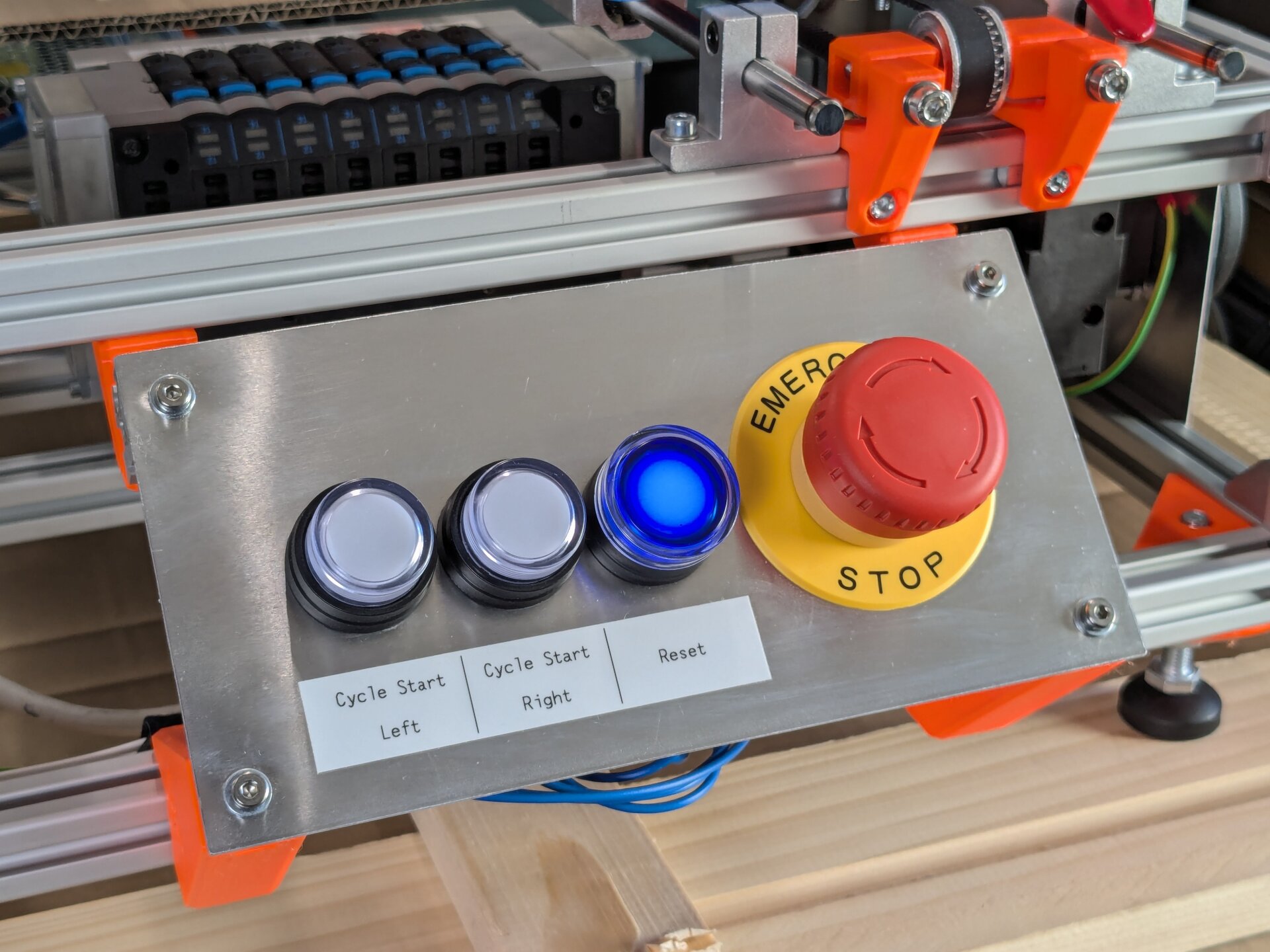
Hardware buttons on the CNC Adhesive Applicator. The buttons are illuminated to indicate their state.
After powering on the machine, the first step is pressing the reset button. This starts movement and the machine begins to initialize itself. This button is also used whenever a fault occurs, to tell the machine that it shall restart again.
After reset, the machine idles, waiting for the left or right cycle start to be pressed. These buttons are used by the operator to indicate that the sled has been loaded and the machine shall start processing it.
All these buttons have an LED lamp that blinks to indicate they can be pressed and lights up permanently to indicate the operation is being performed.
Stack Light
In addition, a stack light provides a global cue about the machine status, with an alarm sounding at the start of movement and when faults occur. The stack light can be seen from further away, providing status feedback at a glance.
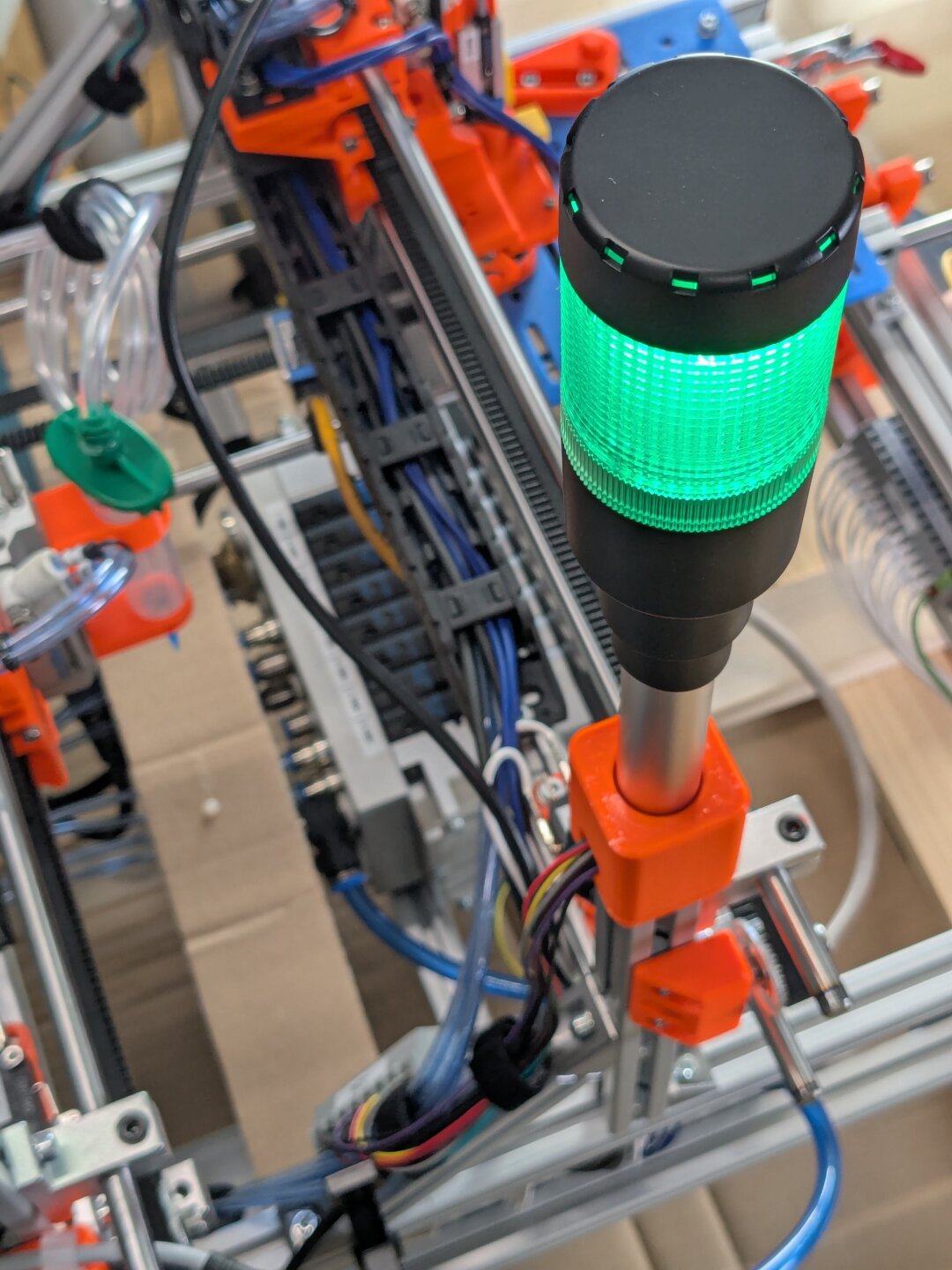
The stack light is mounted at the very top so it can be seen from all around the machine.
After painfully learning that a long tube sticking out from a machine is easily broken during transport, I implemented a magnetic base for the stack light, which allows non-destructively knocking it over.
Oh, and I have written more about stack lights in another blog post: Stack Lights
WEB HMI
Finally, there is a web-based HMI (human machine interface). In production, you do not need to interact with it, it is mainly used for maintenance, commissioning, and troubleshooting.
I am proud to exclaim that no NPM packages were downloaded to make this webpage. There is just a bunch of hardcoded JavaScript to implement interactivity and status updates. And to keep up with current design trends in the industry, I styled the HMI like a Windows 98 application ;)
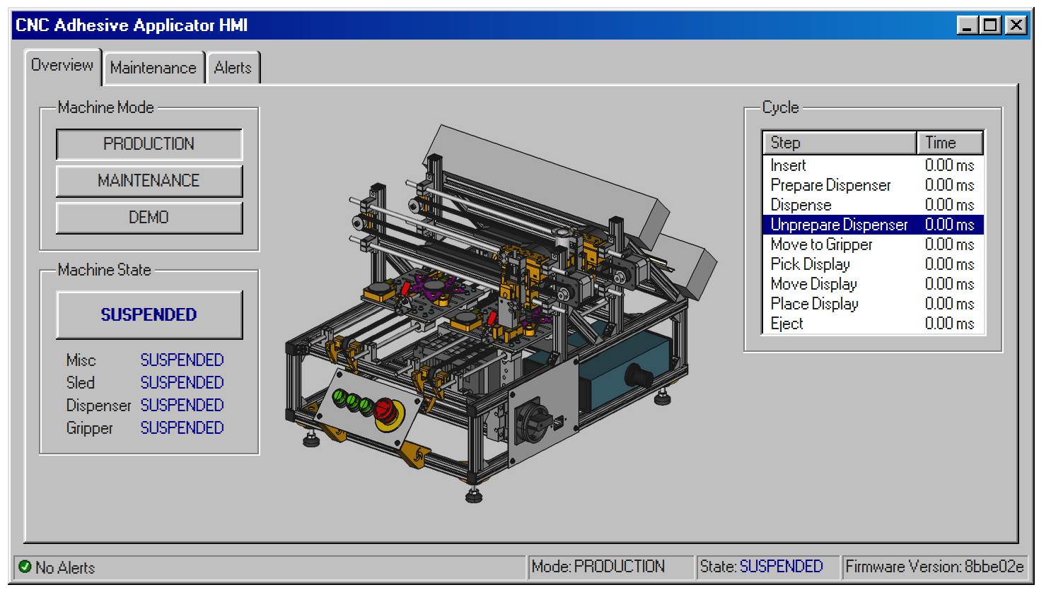
The web HMI that is mainly used for maintenance and commissioning. Here you can see the dashboard where the machine state is detailed and the operating mode can be controlled.
The maintenance page of the HMI has controls for adjusting offsets for the dispensing needle and the pick-and-place gripper. You can also control the dispensing parameters, which is mainly just the movement speed.
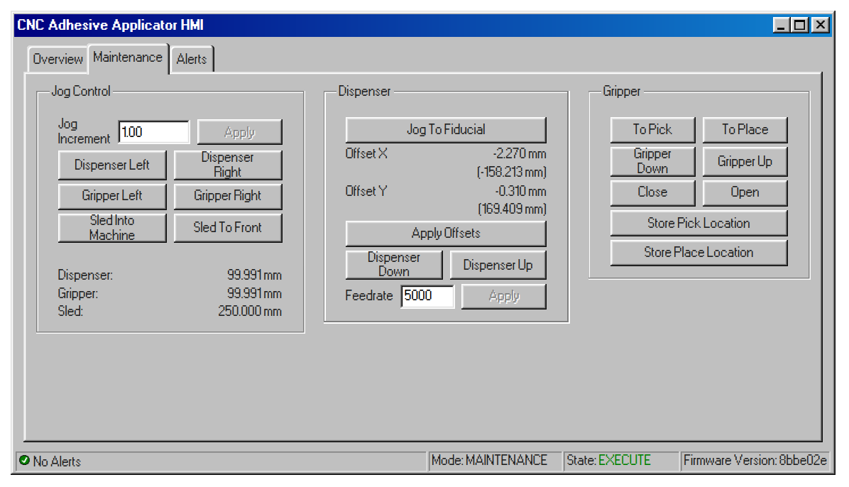
Maintenance screen of the HMI
=B1 Detection of process problems
I have put this topic towards the end because this was not actually implemented, originally. The two detection systems I am going to talk about were both added to the project "post-mortem", with the main intention being the learning exercise of integrating them.
So what is this about? Well, in its original form, the CNC Adhesive Applicator is quite blind — it has to trust the operator that there are really a PCB and a display on the sled and that, for example, no display is already glued to the PCB. The only thing the machine can see is the press of the cycle start button.
For the intended use case, this was acceptable, because there would always be someone watching who could interrupt the process if something is not right. But to improve process reliability, automated machinery should sense its environment as much as possible to detect any issues automatically. This becomes especially important the less a human is present to watch the machine.
To make the CNC Adhesive Applicator "see" what is going on, two additional systems were added:
Display Presence Sensor
The first is a sensor that detects the presence of a display — this sensor can catch situations where the display is missing from the sled or where the pick-and-place mechanism failed to transfer the display to the PCB.
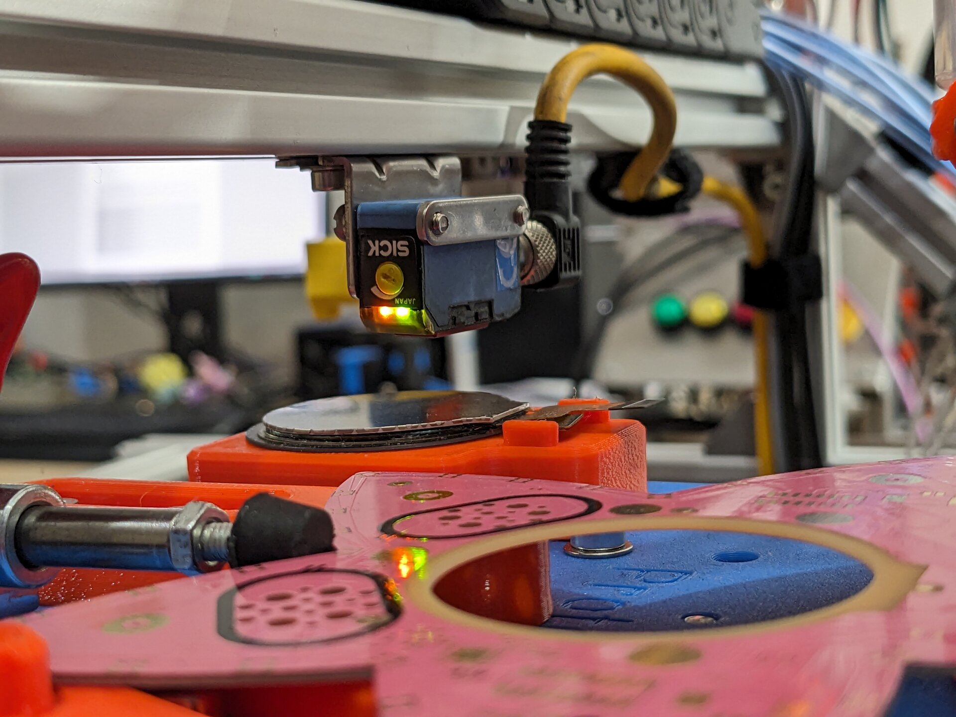
The display presence sensor sensing the presence of a display. Perspective is deceptive in this image, the sensor really sits straight above the display.
This is an optical sensor, often called a photo eye, that detects an object in its proximity by light. To be precise, it is a WT150-P460 with a configurable sensing threshold between 2 and 100 mm. It has a digital output that is either on or off, depending on the presence of an object.
Vision System
The second system quite literally makes the machine see — we added a camera to the pick-and-place gantry. This camera helps with a number of situations:
- Checking the presence and alignment of the PCB
- Checking the correct amount of adhesive (before and after placing the display)
- Correcting for PCB offset based on fiducial markers precisely printed onto the PCB itself
For reliable operation, camera systems need repeatable light conditions. To ensure that, we added an LED ring around the camera lens.
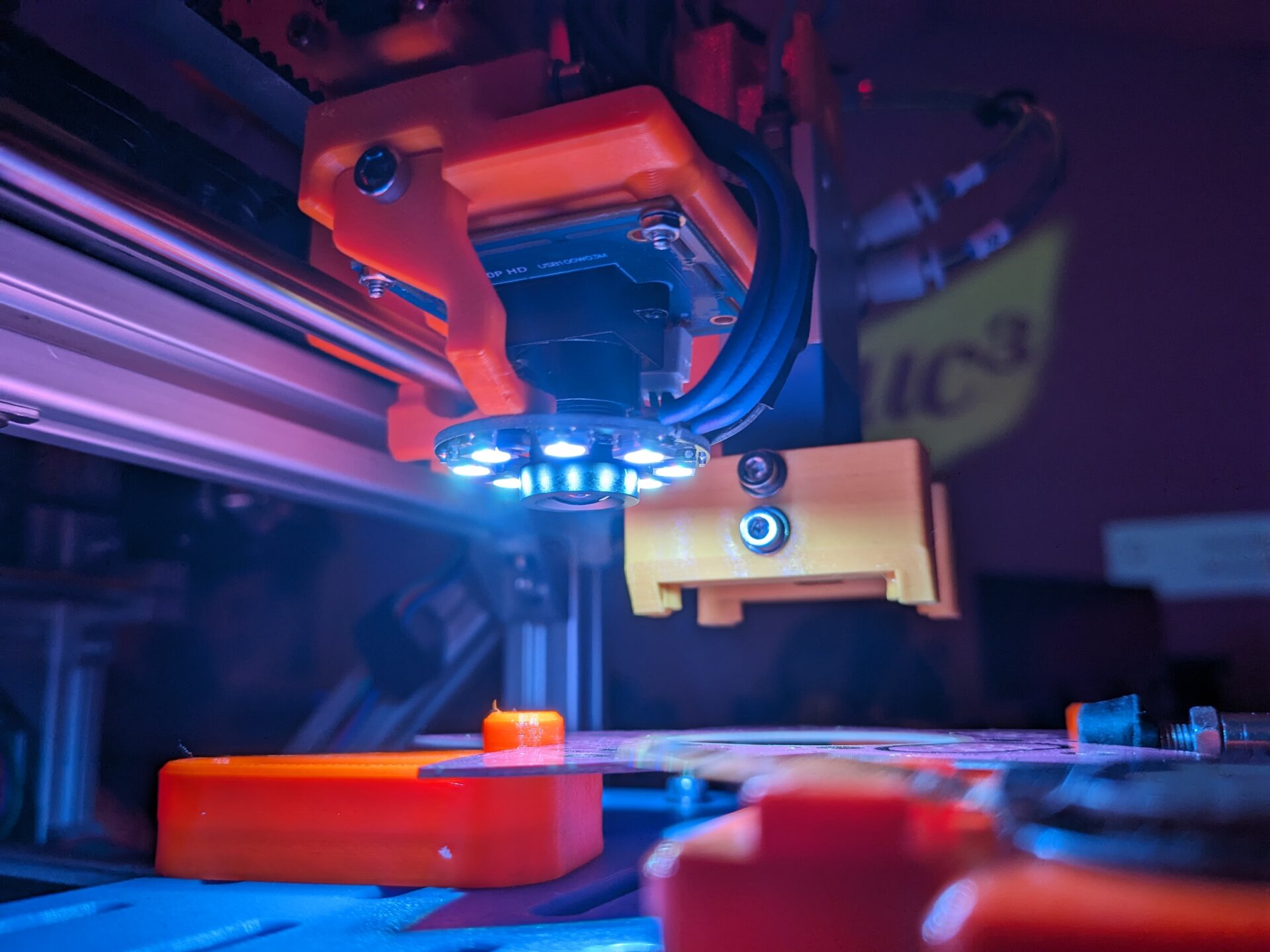
The camera with its LED illumination, looking at a fiducial on the PCB.
We unfortunately never ended up integrating the camera into the control logic of the machine, we only managed to play with fiducial detection a bit. Nonetheless, the system proved to be surprisingly powerful for what little effort was needed to add it.
The camera is a cheap "ELP 720P USB camera module CMOS OV9712".
=G1 Power supply
And finally, a quick one: The machine needs power, of course. So it has a 150W power supply for driving the electronics. Everything is running on 24V DC, the industry standard controls voltage.
Pneumatic energy is supplied via a maintenance unit (FESTO MSB4). It has an electric shutoff valve which is integrated into the safety circuit of the machine. Pressure: 4 bar
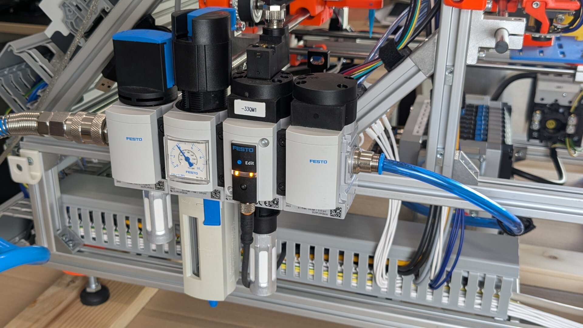
Maintenance unit — left to right: manual shutoff valve, filter-regulator, electrical shutoff valve, soft-start valve
That's all! As you might have noticed, I am very passionate about manufacturing automation — so if you want to know more or have some comments to share, I'd be very happy to get in touch!