This is the next article in the series about our "Flower Machine".
For a fully automatic process, the "raw materials" must also be fed into the machine completely automatically. For the Flower Machine, this means feeding small paper squares one at a time. The obvious storage format is a stack of paper - but how do you pick a single piece of paper from a stack?
Feeding paper reliably was probably the hardest challenge in the Flower Machine project. In this post, I will present all the details it took to get the paper-feeding mechanism working.
Defining the Problem
As always, in the beginning, there was a problem to be solved. Defining it precisely is the first step:
We have a stack of small paper squares and must separate a single one, to move it into the creasing press. The paper squares are from varying types of origami paper, with different thicknesses and surface textures. We decided to fix the size of the papers to 35mm x 35mm. The mechanism must be able to cope with small dimensional tolerances, though. Finally, it should be possible to store a large number of papers in the feeder so the machine can run uninterrupted for a long time.
Experimenting
As we had no idea where to start, we began by researching industrial paper-feeding solutions. We identified two main approaches:
- Lifting the topmost paper from the stack using vacuum suction.
- A "friction feeder" design where a paper is dragged off the stack using rubber belts.
To gather experience and to find out where the difficulties lie in each approach, we started experimenting. The first attempt was a simple paper tray, filled with a stack of paper. A vacuum suction cup lowers from the top and hopefully picks up a single piece of paper.
Well, this didn't work at all. The thin sheets of origami paper allow so much air to pass through that two or even more papers got picked up at once. We tried reducing the vacuum suction but this didn't help either: Now pick-up was even less reliable because sometimes nothing got picked at all.
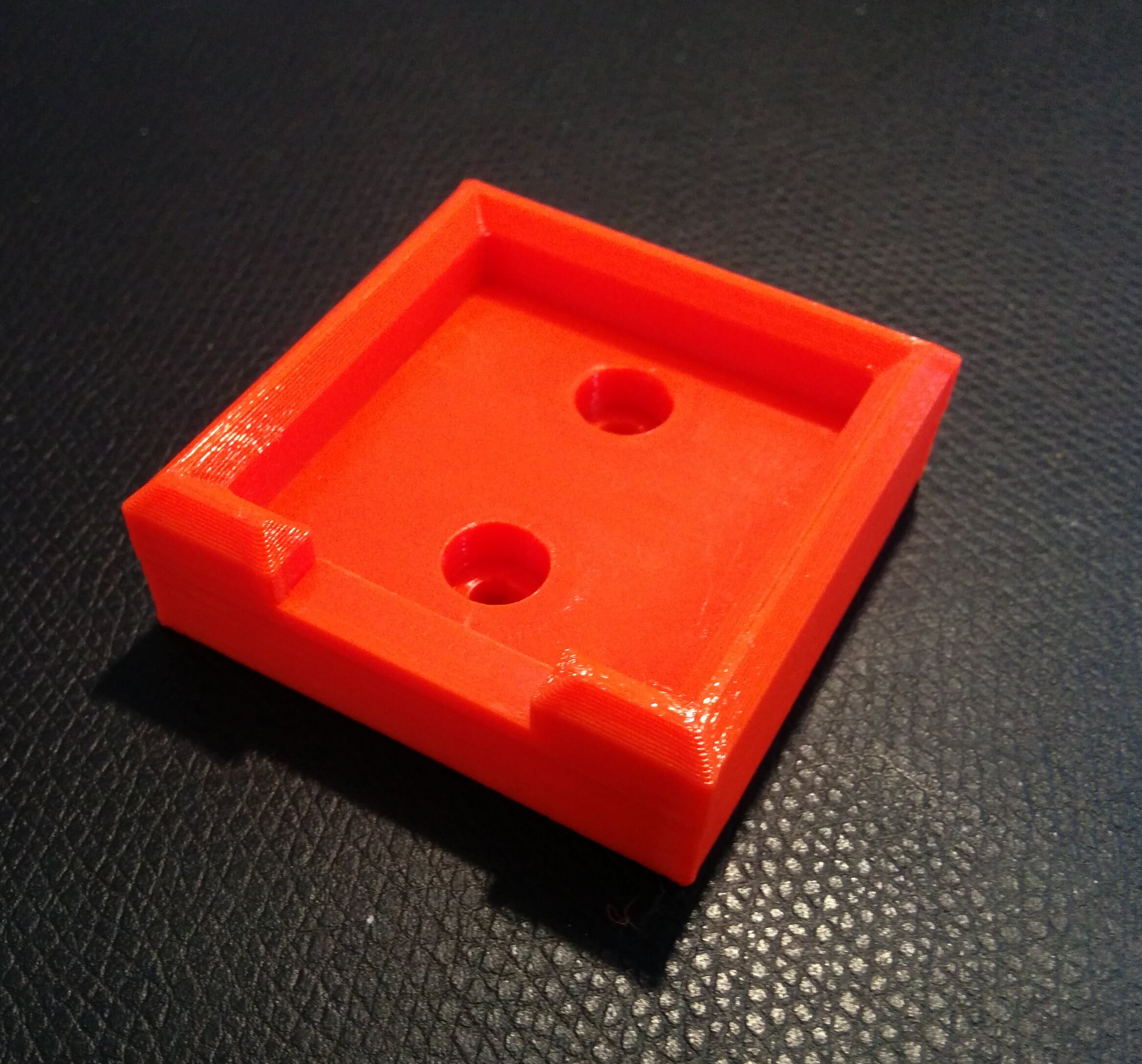
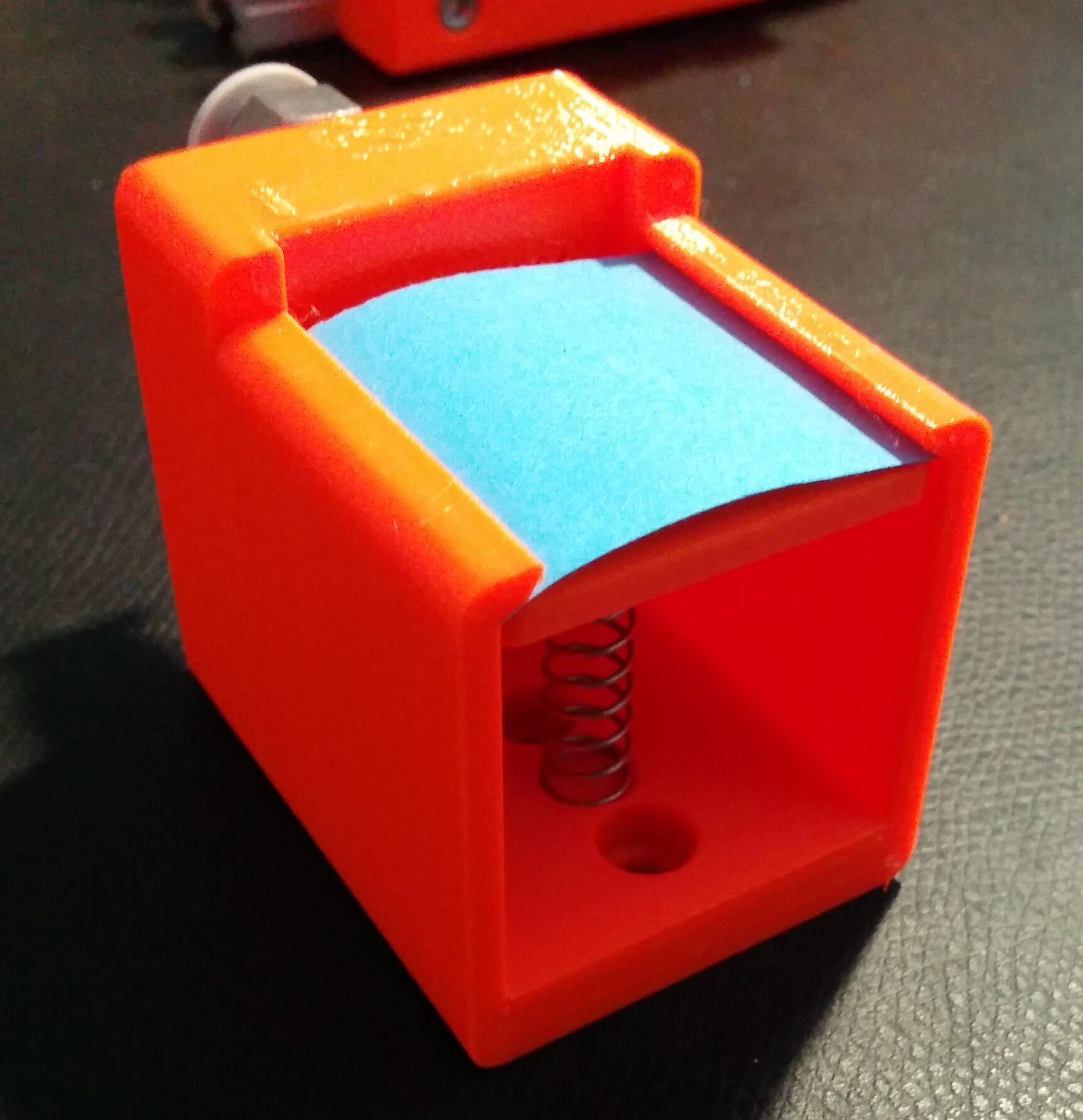
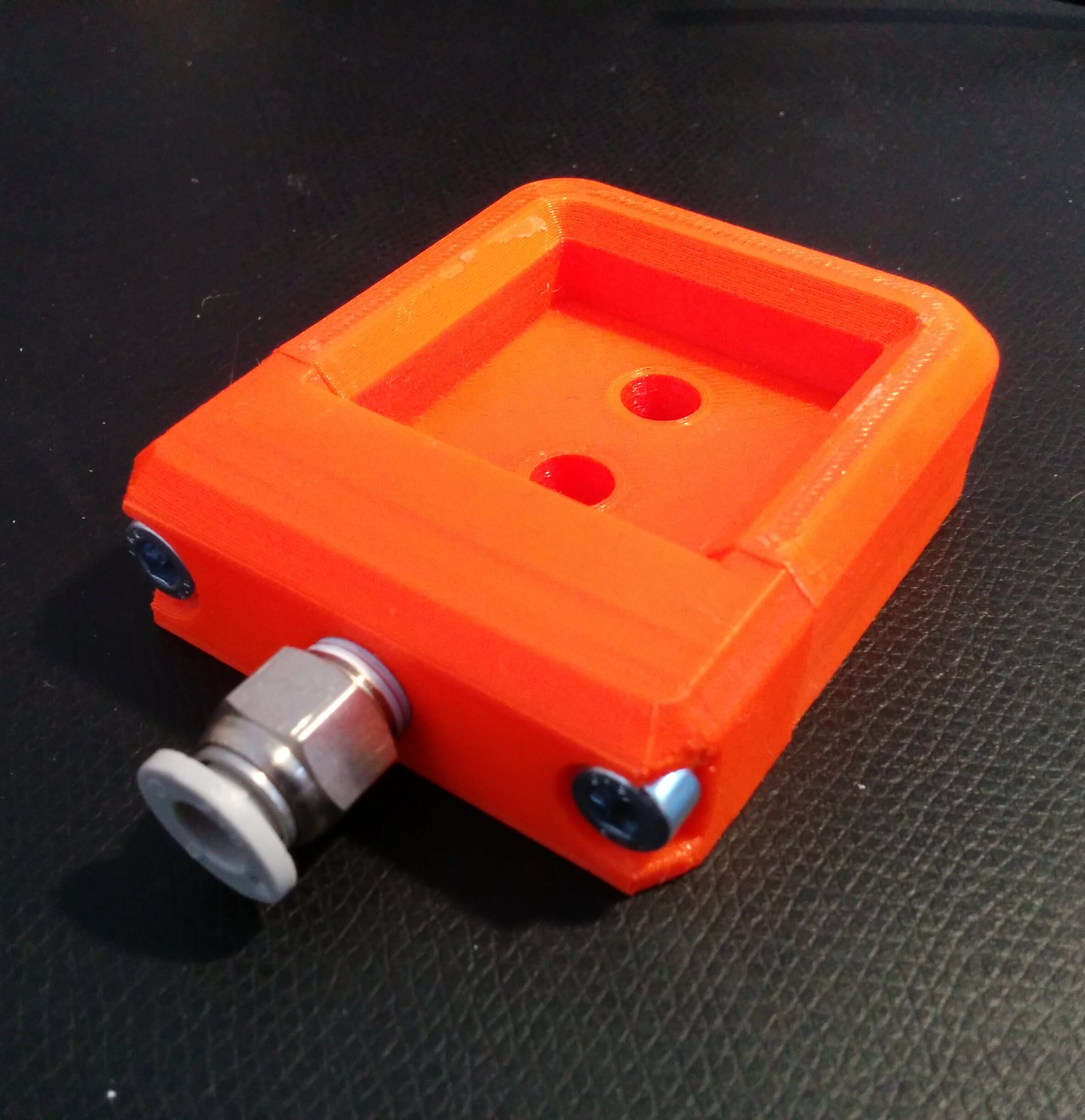
So we looked at possible improvements. One trick we found is blowing air into the side of the paper stack to pre-separate the sheets. A spring on the bottom slightly pushes the paper stack against guard lips on the top which retain the papers so they don't just spill out. When the topmost piece of paper is picked, it is pulled out from underneath those lips.
When we gave this a shot, the papers would indeed get slightly separated by the air. However, we still couldn't reliably pick single pieces. With this design, we often freed multiple papers from the guard lips. The spring force varying with stack height also did not help.
Out of curiosity we also tried a variation where air is blown in, but no guard lips or springs exist. Just a tray with slight airflow for paper separation.
While extremely sensitive to the flow of the air blown in, it was quite interesting to see how it was indeed possible to slightly levitate the topmost paper off the stack. However, this also didn't help us much because the suction cup disturbed the system too much and thus we couldn't reliably pick with this approach either.
It seemed that origami paper just doesn't work with these methods. So we started experimenting with the other approach mentioned earlier: Friction feeder designs.
Friction Feeders
Okay, what is a friction feeder? It is a mechanism where friction between the paper and some rubber parts is used to separate single sheets from a stack. These friction feeders are mostly found in applications where high feed rates are required as they can separate papers incredibly fast (example video).
Most friction feeders are based on the same basic design. Check this video for a quick visualization:
Let's dissect the mechanism a bit:
- The rubber belt below the stack pushes the bottom-most paper forward.
- Due to static friction, usually, more than one paper will be pulled along.
- To separate the sheets, a rubber roller or block (called stripper) applies friction from the top. The gap between the bottom belt and the stripper is set precisely such that a single piece of paper can slide forward on the belt. Further papers experience too much additional friction from the stripper so they are held back.
To make such a design work reliably, many friction forces need to be balanced against each other. Understanding the interaction of all these forces was key to building a design where papers could be fed reliably. Take a look at the following picture:

Friction interfaces involved in friction feeding.
Importantly, notice how there are different friction forces in the paper stack and beneath the stripper. This difference is caused by the paper stack pushing down with a different force than the stripper roller. To make things worse, the force applied by the paper stack changes as the stack empties.
Additionally, there will be static friction in some places which transforms into dynamic friction as the stripper does its job. The dynamic friction will be much lower, of course, so the balance of forces is changed drastically.
Finally, these forces also vary with the kind of paper being fed. Thicker papers generally make things more forgiving. Of course, the origami paper for the Flower Machine is very thin... Essentially this means that small variations will influence feeding behavior more drastically.
All this theory might seem quite complex. But luckily it gets a lot simpler when you consider what variables are controlled to influence the mechanism. In the end, there are really only two (or maybe three):
- The gap between belt and stripper.
- The downward pressure of the paper stack.
- (The speed of the belt. Although in practice, the influence of belt speed is marginal.)
So, let's try building a friction feeder design then...
Flower Machine Friction Feeder
The first challenge was encountered before even starting with the design. The Flower Machine was supposed to run entirely on pneumatics so the use of a belt would be pretty difficult. Instead, an alternative was needed which is driven solely by a pneumatic cylinder. The choice was a "sled" with a rubber surface that is pushed forward by the cylinder and pulls the paper along. It then retracts back beneath the paper stack, where it waits until the next paper should be fed.
Sled & Paper Tray
The sled design immediately brought along another obstacle: While retracting, the sled can't simply move back linearly as this would lead to the bottom of the paper stack crumpling. So the sled needs to move down slightly while retracting and only move back up to its original height once fully retracted. We solved this using a sort of rail system:
Surprisingly, this rail system worked on the first try and never led to any major problems. Only one difficulty needed to be solved: When the sled jumps back up, it would fling the paper stack out of the feeder. To counteract this, we added a lid with a spring to keep the stack in place. This also came with another advantage: The ability to somewhat control the force of the paper stack pushing down.
When refilling the paper feeder, the lid can be removed quickly using a machine handle. These handles are standard parts for tool-less threaded connections. It is worth familiarizing yourself with these as they have a lot of applications. Check this video if you want to learn more: Mechanical Design: Handles - TeamPipeline
I learned about these machine handles quite late in the project. The first iteration of the feeder design used M5 screws to hold the lid down. This meant that an allen key was needed to remove the lid. The new design with the machine handle does not need any tools and is very fast to open.
Here's a demonstration of the refill process:
Stripper Block
With the stack of paper in place and a sled mechanism to feed the bottom-most paper forward, the next part we need is the stripper block. As described earlier, the distance between the rubber sled and the stripper is critical for achieving correct paper-feeding behavior.
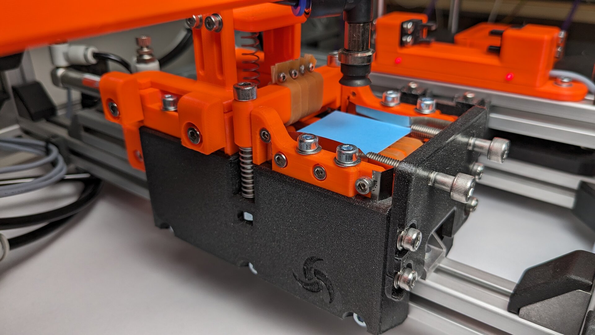
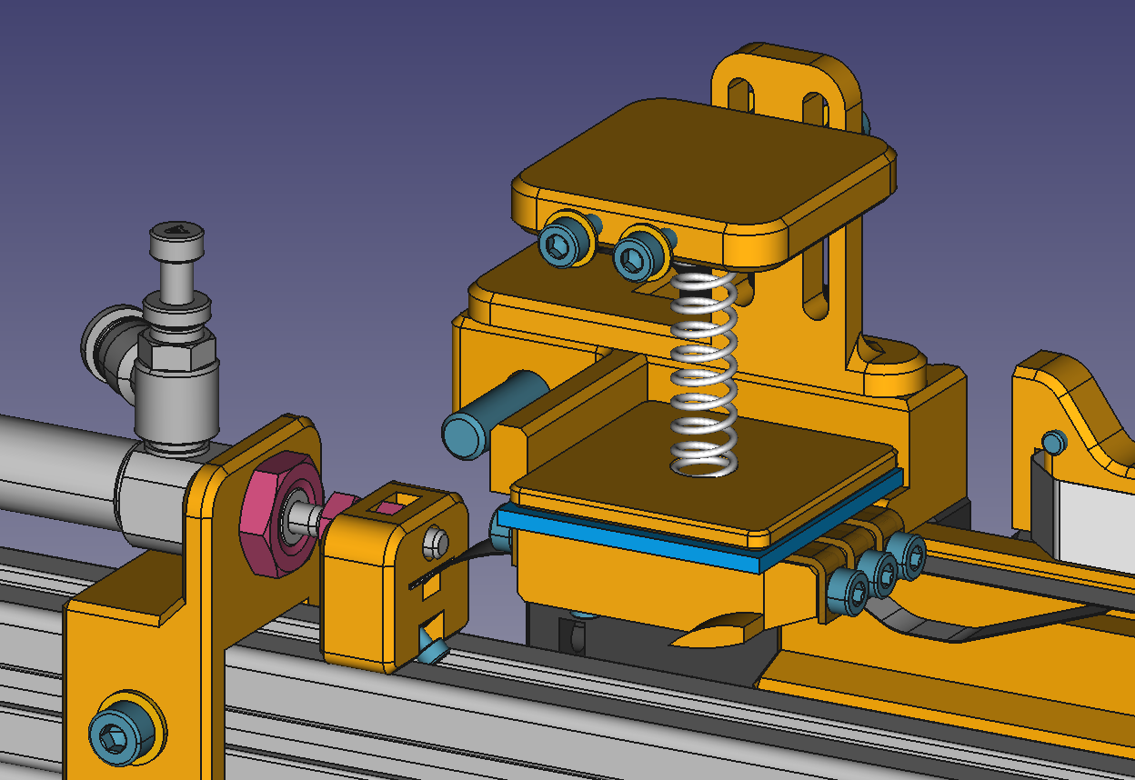
To get this distance right, we added an adjustment mechanism. In the first iterations, this was done using opposing screws. Two from the top and two from the bottom, clamping the stripper block in place. This turned out to make adjusting the distance super tedious as all four screws needed to be adjusted in parallel. In the final design, we instead used two long screws opposed by strong springs. This way, making adjustments got a lot easier and faster.
To generate friction, we used strips of wide rubber bands on both the sled and the stripper block. Initially, we attempted attaching these rubber bands with glue, but this did not work well at all. In the end, the most reliable way to attach them was by poking holes into the rubber and then using small screws.
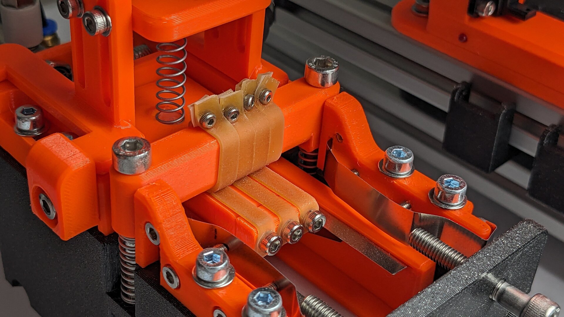
The rubber bands for generating friction are held in place using small screws.
After building the first iteration of this design, we were quite happy to see that it at least somewhat worked. After all the failing attempts with other design approaches, it was quite nice to finally see some results. However, it still did not work reliably. The mechanism would always at some point end up feeding more than one paper, feeding none at all, or feeding a single paper only halfway.
Chasing Repeatability
Figuring out the reason for this inconsistent behavior was a long and painful process. In hindsight, the solution may seem laughably simple but at the time, it really felt like a mystery. Basic attempts at solving the problem never lead to any improvement. It got clear that a different approach would be needed to get to the bottom of the problem.
I think solving this was particularly difficult for me due to my background in software engineering. In that world, you can usually isolate problems quite quickly and thus narrow down the possible causes. You can also iterate on solution attempts very fast which helps to gain a better understanding of the situation.
In the world of mechanical engineering, things work quite differently. Isolating a problem is not really possible on a mechanical contraption. There are much fewer ways to introspect a system's behavior while it is moving (at least with my tools). And design iterations are also quite a bit slower. So what else can we do?
To understand the methodology for solving this, let's first reexamine the problem. At its root, it revolves around repeatability; the system behaves differently each time we test it. Logically, this means that there must be some starting condition that is different for each test. The first step must be finding this condition. Once we know what it is, we can search for the reason why it varies so much.
The plan is as follows:
- Find possible candidates for the source of bad repeatability.
- Destructure the machine into a hierarchical tree of subsystems. The leaves of this tree are the individual components that the machine is built from. Ideally, this tree structure already exists from the design stage of the project.
- Now, start at the root of the tree (which is the entire machine/mechanism) and work your way down.
- For each subassembly/component, list possible ways how it could cause bad repeatability.
- Next, descend into the subassembly and look at each of its components. Who is responsible for the bad repeatability you listed for the subassembly?
- Continue doing this to find the root cause of each possible reason for bad repeatability.
- Now that you have a list of root cause candidates, continue by devising methods for measuring each one. For some of them, it may get quite tricky to get conclusive measurements, while others will be very easy to inspect.
- Once you have an overview, just start with measurements that are very simple to make. The low-hanging fruits, essentially. You may also find some candidates to sound more promising than others, so it makes sense to prioritize these as well.
- While taking measurements, some candidates will be easy to rule out while others will start looking more and more likely. From experience with the paper feeder, you won't find a smoking gun, but rather a group of suspects.
- With all that data gathered, now is the time to iterate on your design. For each of your likely sources of bad repeatability, find ways to improve the design to mitigate them. If you can afford to, don't spend too much time here, but rather build improved designs as soon as possible to see how they perform in the real world.
- Ideally, things got a lot better at this point already. If not, go back to your updated list from step one and run through the sequence again, iteratively moving closer to a working design.
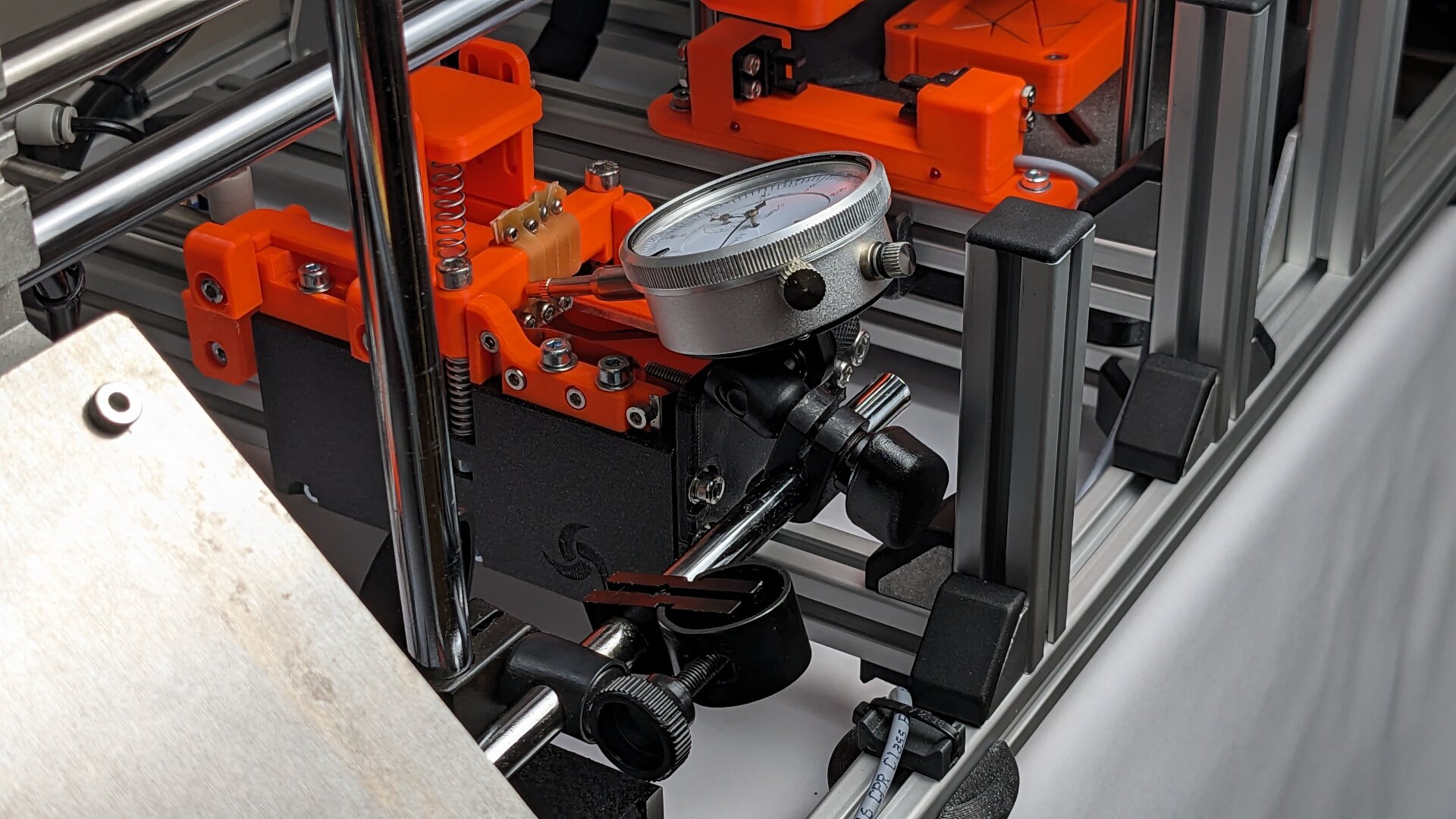
Measuring displacement on the paper feeder.
Yes, this is staged as I unfortunately didn't take any photos while actually measuring the feeder.
Walking through the steps above, among other variability, one main problem emerged in the paper feeder of the Flower Machine: The stripper block was bending while a piece of paper is fed and never returned to quite the same position where it started. This of course influenced the next feeding attempt which again influenced the position of the stripper block.
What's interesting about this is that the bending or flexing of a component by itself isn't necessarily bad for repeatability. As long as the forces involved are the same every time, the bending will behave repeatably. In this situation, however, that wasn't the case, as the bending directly influenced the forces it was caused by. This "feedback loop" lead to the behavior constantly changing.
In fact, if you look closely at the Flower Machine video, which was still shot with the first feeder design iteration, you can actually see the stripper block bending. What you can't see is the variation of its resting place. But after measuring it with a dial gauge, it became apparent quite quickly.
The solution? Making the stripper block as rigid as possible. Ensuring that it is well supported in the direction where forces are exerted on it.
These changes required a rather big redesign of the mechanism. Such a redesign feels scary, but in reality, it is a big opportunity. Big changes usually have the largest impact. And when many parts need to be changed anyway, you can also fix a lot of other minor problems along the way.
Once we had built the new design iteration of the paper feeder, the behavior got a lot better. After getting the feeder adjusted, it started feeding reliably, with only a few misfeeds when the paper stack got close to empty. Finally!
Presenting Precisely
While the mysterious misfeeding was a critical problem to solve, a second topic was no less important: After separating a single paper from the stack, it must be presented to the vacuum suction cup in a precise location and orientation. Any offset in the pick-up location will translate into the same offset in the place location inside the creasing press. Thus, papers that are not picked up in the right position will get the pattern creased with an offset.
We identified two main problems:
- The friction isn't always equal on both edges of the paper. This leads to the paper rotating while it is pushed forward.
- The papers are not always pushed forward the same distance because they are not resting on the sled in the same position each time.
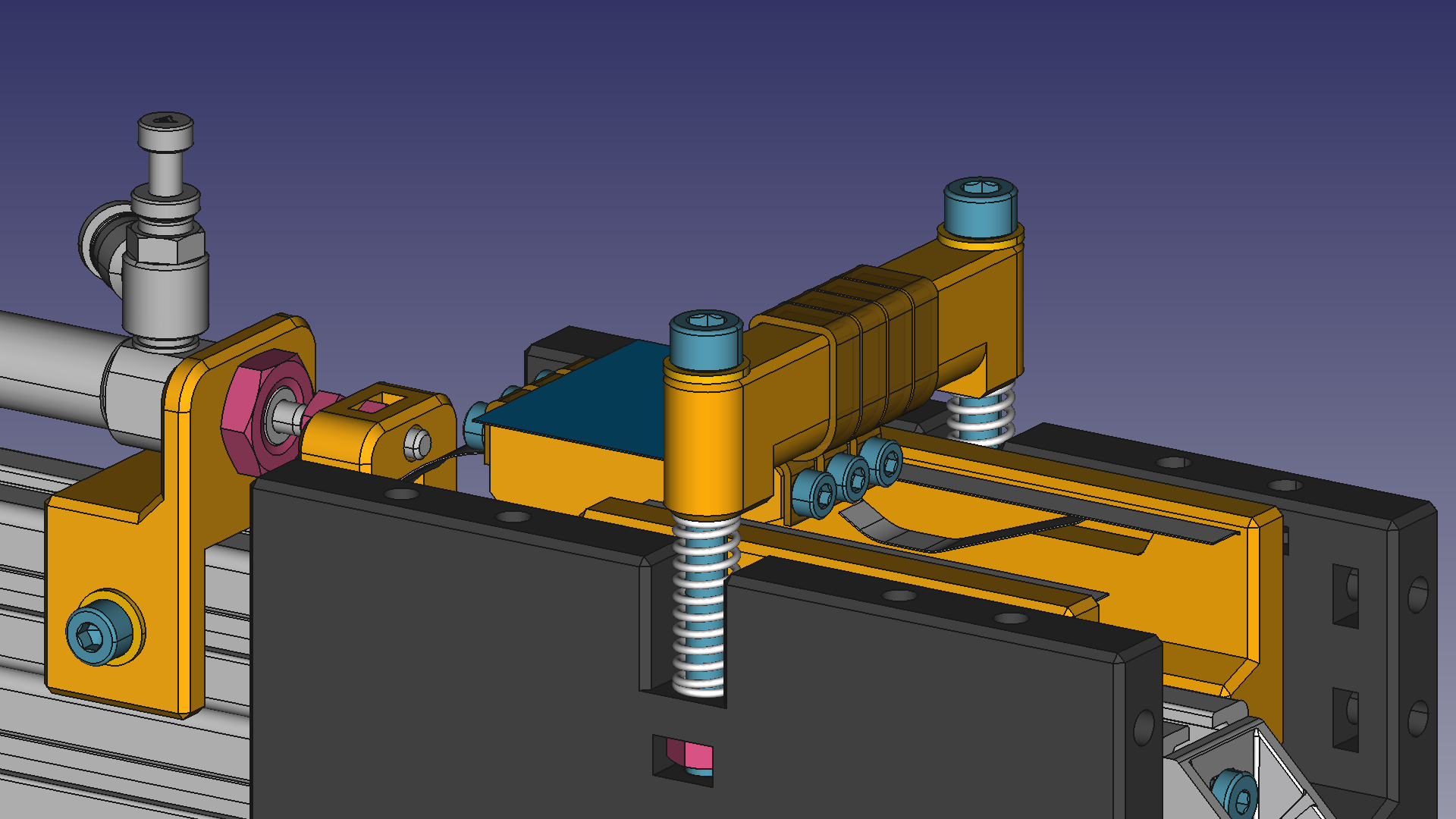
To improve this, we added a set of guides and stoppers which nudge the paper into a precise location for pick-up. To allow fine-tuning the pick-up location, these guides were designed to be adjustable in all possible directions.
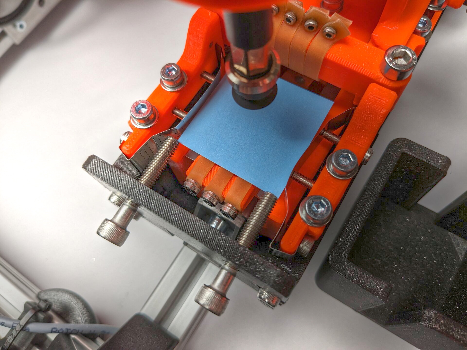
You can see two rails made from spring-steel bands which guide the paper left and right. There are screws that adjust the shape and position of the rails. Then, there are these two M5 screws that stop the paper in a precise position and orientation.
Ready for Mass Production
After changing the stripper block, adding the guides, and a lot of iterative adjustments, the paper feeder was finally starting to work reliably enough for mass-producing paper flowers. There are still occasional misfeeds but they are very rare. I will leave you with a video loop of the paper feeder in action:
You can turn on sound if you want to hear those calming noises of manufacturing machinery!
Want to read more about the Flower Machine project? Head over to the overview of flower-machine posts.