Something not (quite) Flower Machine related for once. I got myself a WAGO 750 remote I/O station with a 750-303 PROFIBUS coupler. This post is documentation how I got it working with the open-source PROFIBUS-DP stack pyprofibus.
Introduction
I want to quickly set the scene for everyone who is not familiar with all this: In industrial automation, lots of signals need to be controlled. Some are logic signals, either on or off, like a limit switch. Some signals are analog, for example the measurement of a pressure transducer. The controller, called a PLC, is usually located quite far away from the actual sensors and actuators. Those are also referred to as field devices, because they are "out in the field". It would be quite cumbersome to run every individual sensor wire back to the controller. Instead, an I/O terminal is placed in proximity to the field devices from where the I/O is distributed. This is the idea of remote I/O stations:

To connect the remote I/O stations back to the PLC, so called field busses are used. These are digital communication networks which allow connecting many remote stations and other devices over a single cable. There are many field busses, but for this post, I will focus on the one that is used in my setup: PROFIBUS.
PROFIBUS can be used for many things, but for this use case, we only need a certain subset of it. This subset is called PROFIBUS-DP. DP meaning decentralized peripherals.
If you want a more in-depth explanation of these concepts, maybe you will find this video useful: What is PROFIBUS-DP by RealPars.
PROFIBUS Wiring
The electrical signaling used by PROFIBUS is RS-485. RS-485 comes with two signals, A and B. Sometimes A is referred to as negative and B as positive. Be careful, the naming differs between manufacturers.
For PROFIBUS, the standard prescribes a special cable which is designed to allow stable communication even in environments with very high amounts of electromagnetic interference. The recommended color is a nice purple.
Further, a DSUB-9 connector is standardized and there are very nice and rugged versions, specifically built for PROFIBUS. They allow connecting two cables, one incoming, one outgoing, and in some cases even have a small switch for enabling bus-termination at this connector. This termination is important for signal integrity of the RS-485.
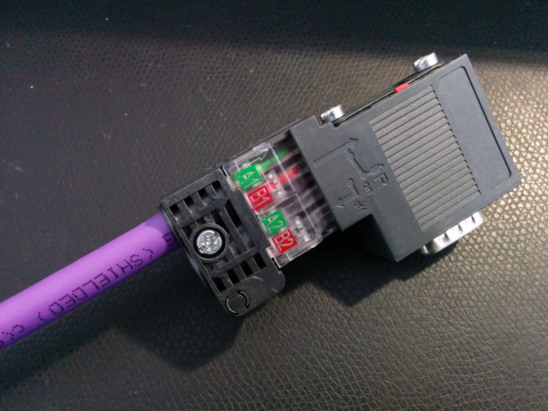
There was one very important lesson I learned here: When you get no responses at all, CHECK. THE. POLARITY. I was spending way too much time, trying to figure out whether I am sending the right datagrams to the right addresses, before noticing I had messed up with something this trivial. Exchanging the two wires was a 30 second job and I immediately got signs of life from my device. At least I will know to check this first, next time around...
Connecting to a PC
On the other end of the cable, I needed a connection to my PC. As my PC isn't
an industrial controller with PROFIBUS built in, some kind of adapter or
converter is needed. Here lies a challenge: PROFIBUS doesn't tolerate
deviation from the required timings. This means the PC and adapter must be
able to respond without too much latency or other devices on the bus will
report errors. The usual way to achieve this would be a dedicated UART/serial
to which an RS-485 transceiver is connected. And then set up the Linux system
for real-time performance (CONFIG_PREEMPT / CONFIG_PREEMPT_RT) and run the
PROFIBUS application at real-time priority.
That is the theory at least. For this super simple setup, I got away without caring about any of that. I bought myself a cheap USB-to-RS485 dongle and I didn't catch any errors caused by it yet. It even works at the far end of my mad cascaded USB-hub jungle.
That said, I wouldn't rely on this setup for any serious usage. The pyprofibus hardware documentation talks about their experience with different options.
Addressing
In a PROFIBUS network, devices have addresses from 0 to 125. Usually, the primary master starts with address 1. 0 is kept free in case a programming station needs to be connected for troubleshooting purposes - address 0 gives it the highest priority so it can hopefully do its job even when everything else is broken...
As I wasn't getting any responses at first, I wanted to scan the entire bus whether there was a response at any of the possible addresses. Sort of like a ping scan in IP networks. PROFIBUS has a datagram for facilitating this, called an FDL Status Request. Sending this request to all 125 addresses should yield a map of all connected participants.
I wrote a small script which you can also find as a gist on GitHub
(profibus_scan.py). And after fixing my polarity error
from above, I got a response!
❯ py profibus_scan.py
Ping   3...
PHY-serial: TX   10 03 02 49 4E 16
Nothing
Ping   4...
PHY-serial: TX   10 04 02 49 4F 16
Nothing

...

Ping  33...
PHY-serial: TX   10 21 02 49 6C 16
Nothing
Ping  34...
PHY-serial: TX   10 22 02 49 6D 16
PHY-serial: RX   10 02 22 00 24 16
FdlTelegram(sd=SD1, haveLE=False, da=0x02, sa=0x22, fc=0x00, dae=Empty, sae=Empty, du=None, haveFCS=True, ed=0x16)
Ping  35...
Nothing

...

Ping 125...
PHY-serial: TX   10 7C 02 49 C7 16
Nothing
Done.
GSD Files
Alright, next step is doing useful communication. But how? For PROFIBUS, each device manufacturer needs to provide a GSD file. GSD stands for Generic Station Description. This GSD file describes all the necessary details for interacting with the device.
For the WAGO 750-303, the GSD file can be downloaded here: https://www.wago.com/us/d/1226
First of all, this description includes details about supported PROFIBUS features. Things like how fast the bus speed may be. Next, the GSD file defines possible configuration parameters and their values. For my device, one such parameter is what behavior should be used when a bus failure occurs. Finally, there is the module configuration. But let's first look at modules in general:
Modular Peripherals
A lot of PROFIBUS devices, including my WAGO 750-303, are modular in their design. This means they consist of a head station which holds the PROFIBUS coupler and then a number of pluggable modules for the actual functionality.
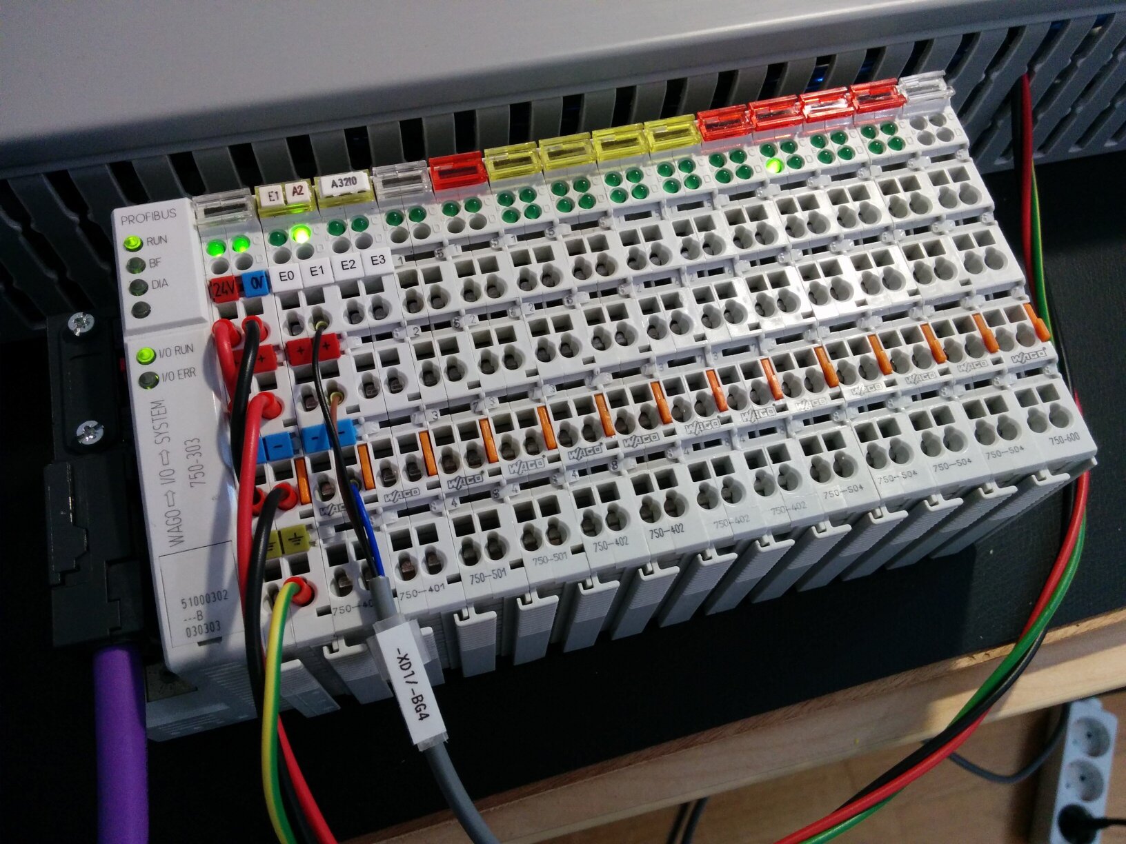
To give some examples, these modules can be digital inputs, digital outputs, analog inputs, analog outputs, or any number of special modules, like a high-speed counter or a PWM output. For my test setup here, I had the following modules connected:
| ID | Amount | Purpose |
|---|---|---|
750-303 | 1 | PROFIBUS-DP Coupler |
750-401 | 2 | 2x Digital Input |
750-501 | 2 | 2x Digital Output |
750-402 | 4 | 4x Digital Input |
750-504 | 4 | 4x Digital Output |
750-600 | 1 | End Module |
Here is the image from the start of the post again, you can probably make out the modules as listed above:
Which modules exist for a given peripheral is defined in the GSD file. It has details about all the modules you may connect. In your configuration, you will then just set a list of modules. This is used for two purposes:
- First, the device validates the configuration against the physically connected modules to check whether configuration and reality match. This way mismatching changes on either side will not go unnoticed.
- Second, the module configuration defines the layout of the process data. That is the data block sent from the controller to the peripheral (outputs) and the data block received back from the peripheral (inputs).
Configuring pyprofibus
pyprofibus usually uses a configuration file for defining the bus connection
method (PHY) and peripherals (slaves). I just named it pyprofibus.conf, but
in the end you just need to reference the filename from your program. I will
show how I have it set up for my environment, going through the config file
step by step. The fragments I will show should all be merged into this one
file.
First of all, especially during setup, you may want to enable debug logging. This allows you to see all communication on the bus and potentially understand where things went wrong:
[PROFIBUS]
; 0 -> no debugging.
; 1 -> DP debugging.
; 2 -> DP and PHY debugging.
debug=2
Next is the bus connection, also called PHY (as it is the physical layer). As I wrote above, I'm using a cheap converter for now. It is set up like this:
[PHY]
; The PHY layer driver type.
type=serial
; The PHY device name/path.
dev=/dev/ttyUSB0
; Only for type=serial:
; Serial line flow control and handshaking
rtscts=False
dsrdtr=False
; The Profibus on-wire baud rate.
baud=19200
Then, we set up the master, that is, the address that we will be communicating from. PROFIBUS-DP knows 3 kinds of masters, with slightly different purposes and capabilities. For this use case, class 1 is the type we need.
[DP]
; The master device class.
master_class=1
; The Profibus address of this device.
master_addr=2
Peripheral Configuration: WAGO 750-303
Finally, we can configure the peripheral (slave). This is a bit more involved and especially it is something that is very device-specific. Every manufacturer does things slightly differently and unfortunately documentation about this topic is quite sparse. I will show how it works for the WAGO 750-303 in hopes that this provides some pointers for other devices. The pyprofibus issue tracker may also contain some valuable crumbs of information here and there.
First, let me show the entire configuration block:
[SLAVE_0]
; Optional name.
name=750-303
; PROFIBUS address
addr=34
; The path to the GSD file.
gsd=B751_P39.GSD
; Module configuration.
module_0= 24 Bit binary inputs
module_1= 24 Bit binary outputs
; The number of output bytes this peripheral transmits
output_size=3
; The number of input bytes this peripheral expects to receive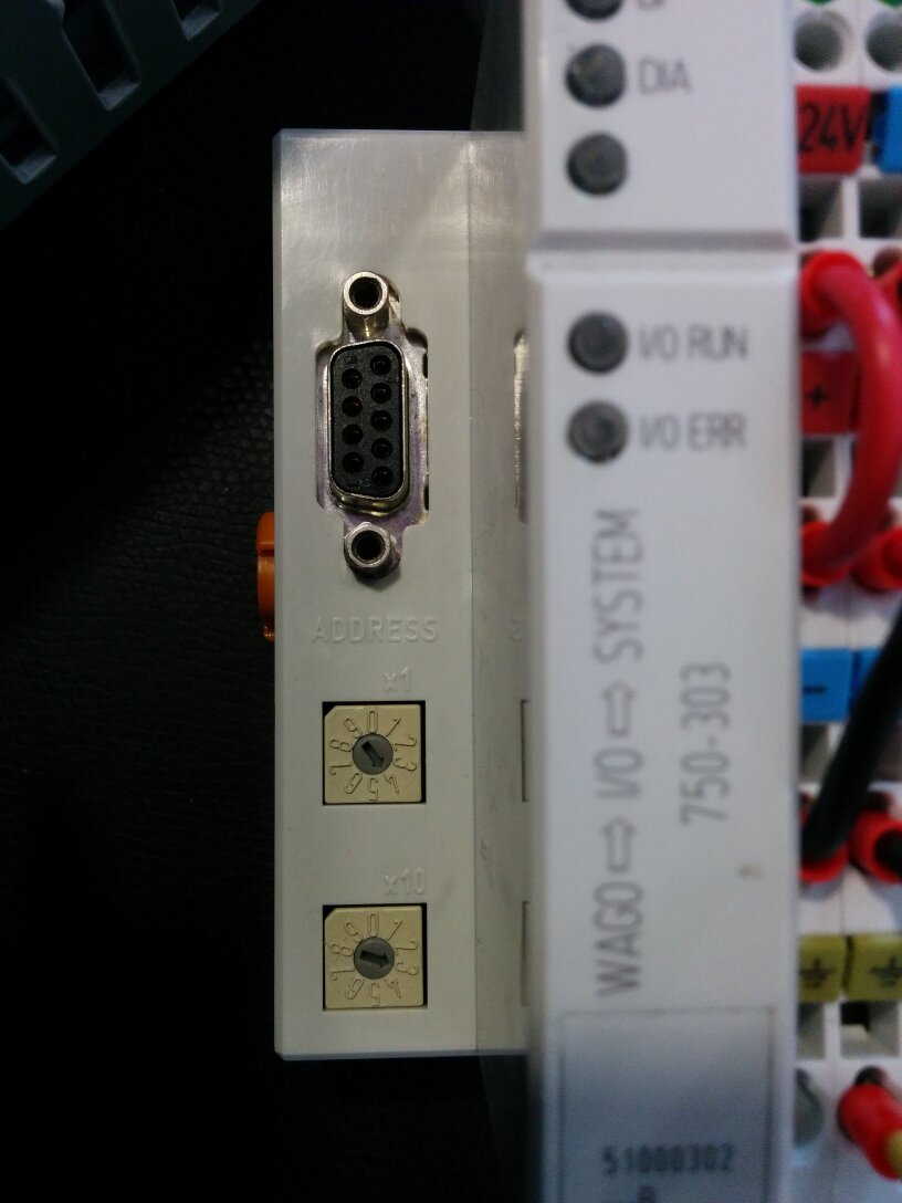
input_size=3nameis optional and for informational purposes only.gsdneeds to point to the GSD file you downloaded from the manufacturer.addrmust be the address configured into the device. For the 750-303 there are two rotary selectors where the address can be customized:
Module Configuration
The hard part is the module configuration. When you get this wrong, the device will just come back with a "faulty configuration" error. Sadly, you don't get much information about what is faulty about it...
Your best bet is finding the appropriate manual from the peripheral's manufacturer. As the module configuration is needed in real industry usage as well, there usually exists at least some documentation about the topic.
For the WAGO 750-303, the relevant manual can be downloaded here: https://www.wago.com/us/d/2701
Chapter 5 of this manual explains how the module configuration works. Particularly, illustration 12 shows an example configuration which I found very useful.
As you can find in the manual, for digital I/O, all inputs and outputs are grouped together into the minimum number of bytes needed in the process data. I/Os are numbered starting closest to the head station. My station has 20 outputs, in modules of 2 and 4 each. All those I/O points are "filled" into 3 bytes (=24 bits) of process data, leaving 4 unused bits at the end. I found the device to be quite liberal in how this setup is represented. All three of the following configuration options work just the same:
; just represent all "real" I/O modules as one "big" module here
module_0= 24 Bit binary inputs
module_1= 24 Bit binary outputs
; just use 8-bit modules until enough bytes are filled
module_0= 8 Bit binary inputs
module_1= 8 Bit binary inputs
module_2= 8 Bit binary inputs
module_3= 8 Bit binary outputs
module_4= 8 Bit binary outputs
module_5= 8 Bit binary outputs ; mixed, to stay true to the physical arrangement
module_0= 8 Bit binary inputs
module_1= 8 Bit binary outputs
module_2= 8 Bit binary inputs
module_3= 8 Bit binary inputs
module_4= 8 Bit binary outputs
module_5= 8 Bit binary outputs Importantly, this liberty in representation only works for the digital I/O modules. Other modules, like analog I/O for example, must be specified exactly as connected.
Beyond this, you will have to specify the total size of the input and output process data in the pyprofibus config. This is luckily something you don't have to get right on your own - the error you get when it is wrong will tell you how much data the device actually sent.
; The number of output bytes this peripheral transmits
output_size=3
; The number of input bytes this peripheral expects to receive
input_size=3
For other PROFIBUS peripherals, this works completely differently. For example, here someone figured it out for the WAGO 750-343: https://github.com/mbuesch/pyprofibus/issues/24
Ship it
After all this setup work, it is finally time to start using the device "productively". I wrote a little script to exercise the I/O station. It just turns on each output one after the other and prints the status of all inputs.
#!/usr/bin/env python3
import contextlib
import time

import pyprofibus


def main():
    # load to the configuration file we created earlier
    config = pyprofibus.PbConf.fromFile("pyprofibus.conf")

    master = config.makeDPM()
    with contextlib.ExitStack() as cx:
        cx.callback(lambda: master.destroy())

        wago750_303 = config.slaveConfs[0].makeDpSlaveDesc()
        assert wago750_303.name == "750-303"
        master.addSlave(wago750_303)

        out_data = bytearray((0x00, 0x00, 0x00))

        master.initialize()

        while True:
            value = 1 << (int(time.monotonic() * 4) % 20)
            out_data[0] = value & 0xFF
            out_data[1] = (value >> 8) & 0xFF
            out_data[2] = (value >> 16) & 0xFF

            for slave in master.getSlaveList():
                if slave.name == "750-303":
                    slave.setMasterOutData(out_data)

            handled_slave = master.run()

            if handled_slave is not None:
                # a communication happened and we got process data back from a
                # peripheral.  In this case there is only the WAGO 750-303, so
                # we don't need to check which peripheral it was.
                in_data = handled_slave.getMasterInData()
                if in_data is not None:
                    print(repr(in_data))

            time.sleep(0.01)


if __name__ == "__main__":
    main()
And that was it, everything is working! As proof, here is a shitty video:
For questions, comments, or anything else, feel free to send me an e-mail!