Accompanying the release of profirust, a PROFIBUS-DP compatible communication stack, I want to provide an introduction to PROFIBUS in general.
While PROFIBUS is quite dated at this point, there are still massive amounts of PROFIBUS installations in service around the world. It's also quite interesting to dig into this bus protocol from a historical perspective — to understand where modern industrial protocols originate from.
What Is A Field Bus?
Before diving into PROFIBUS, we need to talk about at the field bus concept in general. Take a look at the structure of a traditional industrial control system:

As you can see, various sensors signal the state of the machine to the control system. These are called input signals. On the other side, the control system causes reactions using its output signals which are connected to actuators.
The sensors and actuators are called field devices. In the most basic setup, there is a cable running from each field device directly to the control system. This is simple to set up, but of course it does not scale well when the number of field devices increases or when the distance between the control system and its field devices becomes very large.
To solve this problem, a field bus is introduced. Instead of each field device having its own cable to the control system, we run a field bus through the machine, with I/O stations close to the sensors and actuators:

Of course, this cuts down on the amount of cabling significantly. But that is not the only advantage: Due to the digital nature of the bus, we can now send along a lot more information in both directions. Sensor parameters can be remotely configured using the bus. And diagnostics from sensors and actuators can be sent back to the control system to keep track of the equipment's health.
PROFIBUS is one such field bus, but by far not the only one, of course. Others include MODBUS, CAN, or DeviceNet. And for quite some time already, field busses have started to give way to something called industrial ethernet. That's the usage of ethernet-based protocols as a replacement for the older field busses which all had their own physical layer communication technology. To name a relevant one, PROFINET is the ethernet based successor to PROFIBUS.
Setting The Scene: PROFIBUS
Alright, let's dive in. PROFIBUS is short for Process Field Bus. PROFIBUS specifies multiple physical layers and a few application profiles for different communication use-cases. You will also come across the term PROFIBUS-DP a lot, with DP being short for Decentralized Peripherals. More on that later.
Generally, a PROFIBUS installation has one or more masters who are in control of communication. Each master talks to some peripherals (called "slaves" in official documentation), which are the sensors and actuators. Peripherals are passive bus members, they only respond to requests initiated by a master.
Each device on the bus has an address, between 0 and 125 (inclusive). This of course also means that a single bus can handle no more than 125 participants. Address 0 should be reserved for programming/diagnostics devices.
Physical Layer
The most common physical layer for PROFIBUS is a multidrop RS-485 (Wikipedia) bus with a maximum of 32 devices per bus segment. RS-485 was chosen for its robustness against electrical noise which is very prevalent in industrial environments.
PROFIBUS specifies shielded twisted pair cables with one green and one red core for the RS-485 A and B signals. The cable sheath is usually colored purple.
PROFIBUS supports baudrates from 9600 bit/s up to 12 Mbit/s. Most installations run at 500 kbit/s or 1.5 Mbit/s, with the notable exception of anything including servo control - such applications need very low latency and thus usually run at 12 Mbit/s.
Devices are usually connected using a DB9 connector with a PROFIBUS-specific pinout. There are PROFIBUS connectors that make it easy to connect PROFIBUS cables to a device while also feeding the bus onward to the next drop.
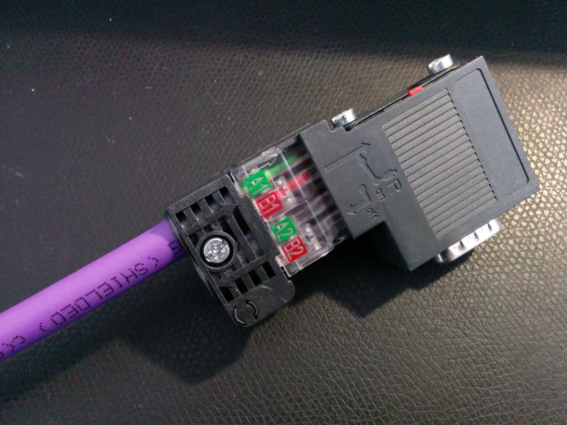
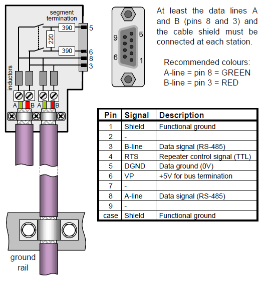
These connectors usually also include a switch that allows activating termination at this device. PROFIBUS always requires active termination which is fed from pins 5 and 6 of the connector as shown below:
Bus termination is a very important topic for PROFIBUS. An overwhelming number of issues in PROFIBUS networks can be traced back to improper termination. For this reason, there is an alternative to the connector-based termination: Dedicated termination modules.
They do not work any different but they have the advantage of decoupling the bus termination from the last device on the bus. Otherwise, when the last device is powered off, the corresponding bus termination is no longer available. By moving termination to a separate module, the "last" device is no longer last and thus does not need special considerations anymore.
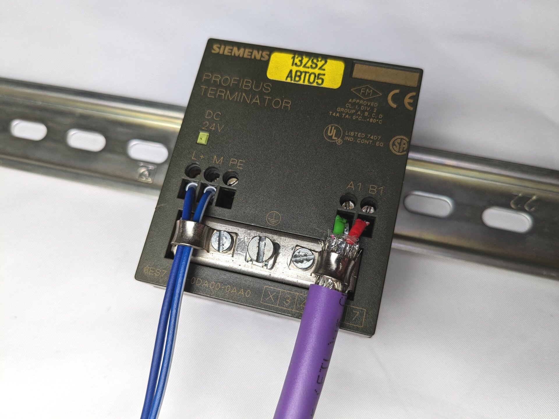
A dedicated active termination module.
There is one more special PROFIBUS device that is worth showing here. As mentioned before, a maximum of 32 devices are allowed per bus segment. This is a constraint of the electrical characteristics of RS-485. To connect more devices, a repeater can be installed, which allows connecting multiple segments to each other. Most repeaters also keeps segments galvanically isolated from each other. This helps with fault tolerance because on large installations, there might be significant potential differences between bus segments. Special diagnostics repeaters also measure bus parameters and help with troubleshooting by providing detailed fault information.
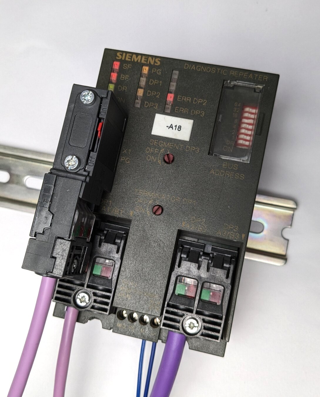
A PROFIBUS diagnostics repeater. Yes, you can see some non-standard cables in this picture...
Physical Layer: MBP
Beyond the RS-485 physical layer, the process industry has a second physical layer as part of the PROFIBUS-PA (Process Automation) profile: Manchester Bus Powered (MBP). This is a wiring scheme where device power is transmitted on the same two wires as the manchester-coded data signals.
In process applications, field devices may be particularly far away from the control system. This makes MBP very useful because it means only one cable needs to be routed to each device.
PROFIBUS-PA segments are connected to a PROFIBUS installation using special DP/PA couplers. For applications where field devices are located in potentially explosive atmosphere, some couplers can act as an intrinsically safe isolation barrier.
PROFIBUS-PA works at a fixed baudrate of 31.25 kbit/s. Baudrate translation between the DP network running at a higher baudrate and the PA segments is done by the DP/PA coupler.
Physical Layer: Optical & Wireless
Finally, there is also the option to include optical (fiber) or wireless links in a PROFIBUS installation. Appropriate transceiver devices are available for this.
I will not go into any more detail on this - the only thing I'll mention is that special considerations need to be made about which side of such links the bus masters are placed.
FDL - Fieldbus Data Link
On top of the physical layer sits the FDL, the fieldbus data link. It provides basic facilities for communication between devices, fault recovery, and resource sharing when multiple masters are active on the bus.
In a working setup, you shouldn't see much of the FDL. However, when things go wrong, you will inevitably stumble into its territory.
FDL: Telegrams
Communication is always performed by sending telegrams from one station to another. A normal telegram has a destination address, a source address, and a data payload of up to 246 bytes.
Additionally, a telegram can optionally specify so-called service access points (SAPs). One for the destination and one for the source. You can think of these SAPs like a UDP/TCP port. SAPs are predefined - for example, the SAP for setting peripheral parameters is 61.
Two special kinds of telegrams work differently from the rest:
- Token telegrams are used to pass on the token from one master to the next — more about that in the next section.
- Short confirmation (SC) telegrams are an optimization to give a quick response without sending any data along. They are just one byte in length and its destination and source must be inferred from the request that preceded it.
FDL: The Token Ring
To arbitrate the bus between all active masters, PROFIBUS uses a token ring. At any time, one master holds the token and is the only one allowed to initiate communication. Once it is done it passes the token to the next master in the ring.
To discover new masters, each existing master will scan the bus periodically. And when a master drops out, or the token gets lost due to an error, a recovery mechanism is used to deterministically assign a new token to one of the masters.
FDL: Basic Communication
When a master holds the token, it can start performing communication as it pleases. The basic scheme is always the same: The master sends a request telegram to a certain address. Then the peripheral at that address is expected to respond with a matching response. It is important for this response to be initiated in a timely manner - there is a strict limit here, called the slot time. Which leads us to the part of the FDL that you will most likely encounter:
FDL: PROFIBUS Timing
PROFIBUS uses time-based mechanisms to manage communication. This has the advantage that worst-case times can be calculated for any bus operation. Most commonly, this is utilized to calculate the overall bus cycle time — the time it takes until data has been exchanged with each peripheral once. This bus cycle time directly influences how fast the control system can respond to inputs, so it is important to know.
While the default values for each timing parameter should usually be good enough to get the bus running, there will be situations where either a complex setup or degraded signal quality leads to the parameters needing to be tweaked.
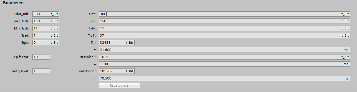
Timing parameters for a PROFIBUS network as shown in SIEMENS' TIA Portal.
The meaning of each parameter is best referenced from the relevant
documentation of the PROFIBUS master. Worth mentioning is the Tslot, the
slot time mentioned before, and the Retry limit, the number of retries when
no response is received for a telegram. Do note that no retries should be
necessary on a properly installed PROFIBUS network.
PROFIBUS DP - Decentralized Peripherals
With the FDL covered, we can now move closer to the application layer. For the overwhelming part, this will be PROFIBUS DP — where DP stands for decentralized peripherals. DP specifies how peripherals are configured, how data is exchanged with them, and how diagnostics are reported.
There are multiple versions of DP, supporting increasingly complex use cases. The most simple one, DP-V0 specifies cyclical data exchange. DP-V1 adds support for acyclical communication and DP-V2 even allows for broadcast-style communication. Of course, the later versions add a whole load of other new features as well.
For this introduction, I will focus on DP-V0 as that is still the most common communication type.
DP: Modular Peripherals
DP knows two types of peripherals: Modular and compact. A modular peripheral is made up of a head station to which several modules are connected. A compact peripheral does not support any kind of modularity. To give an example, here is a WAGO remote I/O station (a modular peripheral) with a few different I/O modules:
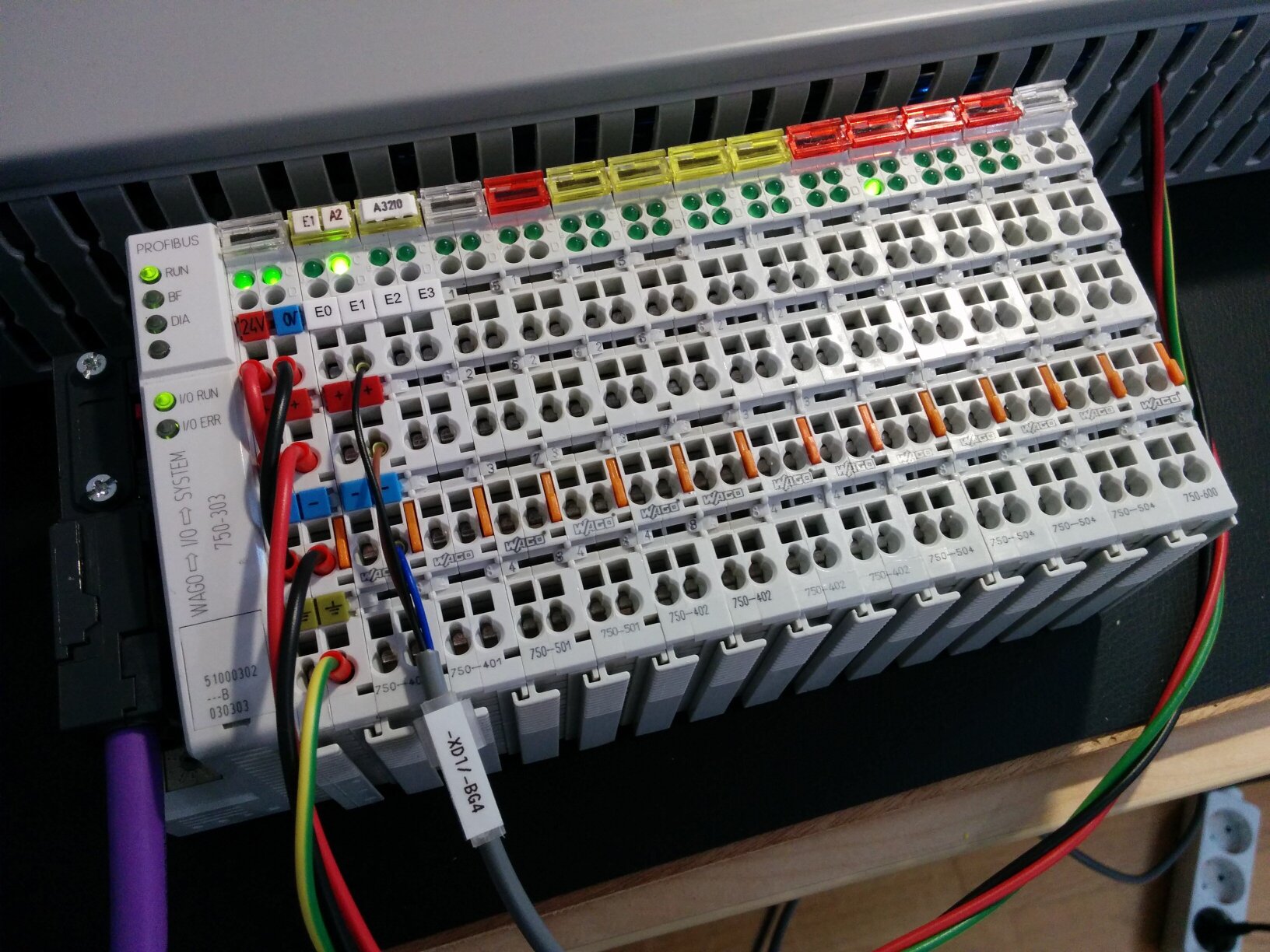
WAGO 750-303 remote I/O with different input and output modules.
In practice, almost all devices pretend to be modular peripherals, even if they do not consist of physically exchangeable modules — instead, they use the modularity mechanism so you can choose different configurations or operating modes in software.
DP: GSD Files
Talking about configuration, it is time to introduce GSD files. GSD is short for Generic Station Description. These files are shipped with every PROFIBUS peripheral and describe everything the bus master needs to communicate with it:
- Identifiers (
Ident Code= a 16bit unique device identifier, Name, Vendor) - Capabilities (Baudrates, Features, Fail-Safe)
- Parameters (Device specific things like measurement resolution)
- Modules (Available modules, possibly with per-module parameters)
- Diagnostics
GSD files are human-readable but generally, they are used by PLC programming packages to provide a nice user interface for setting up your peripherals. There, you'll set parameter values and configure the modules that the peripheral is expected to have.
To give a practical example, here is a possible set of settings and modules for the I/O station shown above:
Global Parameters:
  - DP-Watchdog-Base...............: 10 ms
  - Restart on K-Bus Failure.......: POWER ON RESET
  - Device Diagnosis...............: enabled
  - Process Data Representation....: MOTOROLA (MSB-LSB)
  - Response to PROFIBUS DP Failure: Substitute Values are switched
  - Response to K-Bus Failure......: PROFIBUS communication stops

Selected Modules:
  [ 0] 750-343 No PI Channel
  [ 1] 750-401  2 DI/24 V DC/0.2 ms
  [ 2] 750-401  2 DI/24 V DC/0.2 ms
  [ 3] 750-501  2 DO/24 V DC/0.5 A
  [ 4] 750-501  2 DO/24 V DC/0.5 A
  [ 5] 750-402  4 DI/24 V DC/3.0 ms
  [ 6] 750-402  4 DI/24 V DC/3.0 ms
  [ 7] 750-402  4 DI/24 V DC/3.0 ms
  [ 8] 750-402  4 DI/24 V DC/3.0 ms
  [ 9] 750-504  4 DO/24 V DC/0.5 A
  [10] 750-504  4 DO/24 V DC/0.5 A
  [11] 750-504  4 DO/24 V DC/0.5 A
  [12] 750-504  4 DO/24 V DC/0.5 A
And if you are really curious, the GSD file for the WAGO 750-343 I/O station can be downloaded here: https://www.wago.com/us/d/1226
DP: Peripheral Setup
After you have configured all peripherals in your project, the bus master will attempt setting up the peripherals using your settings. To start, it periodically polls each known peripheral until they show up. Once a peripheral appears, the master first sends parameter data, then the module configuration, and then checks whether the peripheral accepted those settings.
If it did, great, the peripheral is now ready for data exchange.
If the peripheral rejected the settings, you will need to dig in and troubleshoot them. As long as you generated parameter data and module configuration using the appropriate GSD file, the most likely error is an incorrect module config. Make sure that the modules physically connected to the peripheral match the modules in your config exactly.
DP: Cyclical Data Exchange
After the setup, the peripheral is ready for "production use". PROFIBUS calls this cyclical data exchange. In this state, the bus master periodically sends output data to the peripheral which then replies with the latest input data. This communication is performed once every bus cycle, hence the naming.
DP: Process Images
The data that is sent as inputs and outputs is sent as so-called process images. A process image really is nothing more than a chunk of memory. Individual bits and bytes in this memory are assigned meaning, depending on the functionality of the peripheral. For our purposes, two process images are important:
- The process image of inputs (PII), containing data from the peripheral for the PLC (bus master).
- The process image of outputs (PIQ), containing data sent from the PLC to the peripheral.
The full process images for a peripheral are simply a concatenation of the process images for each module. The module configuration, as found in the GSD file, tells you how many bytes of inputs and outputs a module expects.
To give an example, a 4-channel digital input module might expect one byte of input data and zero bytes of output data. The 4 least significant bits in the input byte indicate the state of the channels.
Or a two-channel analog input module might report 4 bytes of input data. The first two bytes are the 16-bit unsigned value of the first channel and the last two bytes contain the value of the second channel.
DP: Diagnostics
Of course, at some point, something will go wrong. A peripheral can indicate such situations to the master using DP's diagnostics mechanism. When diagnostics become available, this is signaled as part of the next cyclical data exchange. The master then polls diagnostics from the peripheral to find out what is wrong.
To decode the diagnostics data, the GSD file should contain the necessary information. In practice, this means giving human-readable descriptions for individual bits or textual value representations for bitfields.
Click to expand an excerpt from the GSD file for a SIEMENS diagnostics repeater.
(
Unit_Diag_Bit(X)means if bitXis set, the given fault is active).; Bit A.0 Unit_Diag_Bit(112)="Fault location, cause unknown" ; ; Bit A.1 Unit_Diag_Bit(113)="Fault unknown (Fault A.1)" ; ; Bit A.2 Unit_Diag_Bit(114)="Fault unknown (Fault A.2)" ; ; Bit A.3 Unit_Diag_Bit(115)="Further DR wired up with DP2" ; ; Bit A.4 Unit_Diag_Bit(116)="Further DR wired up with DP3" ; ; Bit A.5 Unit_Diag_Bit(117)="Fault unknown (Fault A.5)" ; ; Bit A.6 Unit_Diag_Bit(118)="Fault cause unknown" ; ; Bit A.7 Unit_Diag_Bit(119)="Critical frame error rate" ; ; Bit B.0 Unit_Diag_Bit(120)="Break on signal line A" ; ; Bit B.1 Unit_Diag_Bit(121)="Short-circuit to shield on B" ; ; Bit B.2 Unit_Diag_Bit(122)="Fault unknown (Fault B.2)" ; ; Bit B.3 Unit_Diag_Bit(123)="Short-circuit to shield on A" ; ; Bit B.4 Unit_Diag_Bit(124)="Break on signal line A" ; ; Bit B.5 Unit_Diag_Bit(125)="Fault unknown (Fault B.5)" ; ; Bit B.6 Unit_Diag_Bit(126)="Break on line A/B no resist." ; ; Bit B.7 Unit_Diag_Bit(127)="A/B shorted, too much resist."
PROFIBUS Application Profiles
At this point, PROFIBUS DP provides a generic communication mechanism for any kind of peripheral. To standardize things a bit more for similar kinds of peripherals, a few different application profiles exist. These profiles constrain how certain types of peripherals should communicate to allow for cross-vendor compatibility and to make the control system less dependent on the concrete peripherals being used.
Most well-known, PROFIdrive is an application profile for motion control applications. It provides a standardized interface for any kind of motor driver, ranging from simple speed-controlled motors to servo drives with very precise positioning capabilities (More info at profibus.com).
Another profile worth mentioning is PROFIsafe, a profile for implementing functional safety applications over PROFIBUS (Wikipedia).
And that's about it. Of course, all those topics go way more in-depth than what I have covered here. And sadly, information about PROFIBUS is relatively obscure. Well, outside of the industries where it is used, the protocol doesn't have much relevance anyway. But I hope this blog post can at least shed some light on PROFIBUS, beyond the usual surface-level non-technical introductions you can find elsewhere...
And finally, if you happen to be more involved with PROFIBUS, I'd love to get in touch. And please do let me know if some of the information on this page is not correct — I've assembled it with my best intentions from all I know, but I need to be clear that I am rather new to the PROFIBUS world as well.