Over the past years, I have gotten deeper and deeper into 3d-printing. One thing that fascinates me a lot is how different it is from other manufacturing methods. And how this, in turn, means a completely different design philosophy is needed to create good designs for 3d-printing.
As such, I have been collecting the little tricks and rules for designing well-printable parts. And of course I am always on the hunt for more. In this blog post I want to share all that I have learned.
Introduction
While a lot can be found online about the basics of design for 3d-printing, there is not that much material that dives into it in-depth. And even less common are good overviews that collect all the little tricks that people have discovered.
I believe the best format for teaching the rules of well-printable design is a format that is built on rules of thumb and many practical examples. While such heuristic rules will never encompass the whole complexity of the real world, I think they can provide a tangible guide towards the best solution in each situation. They also provide a starting point for building your own intuition about the topic.
This approach is close in spirit to the german book Konstruktionspraxis im Maschinenbau by Gerhard Hoenow and Thomas Meißner (Hanser Fachbuch, ISBN 978-3-446-46485-8). The book follows the same philosophy, but for traditional manufacturing methods. If you like this style, that book might interest you as well.
Scope
Before diving in, a few words about the scope of this blog post: First, I am explicitly focusing on FDM/FFF printing (Wikipedia). A lot of the rules are specifically tied to the restrictions of this process and do not apply to other additive manufacturing methods.
Second, I am focusing on designing functional parts with optimal mechanical properties. These parts should be easy to print, without requiring much printer fine-tuning. They should be easy to produce in higher quantity, which means they should require as little post-processing and waste as little material as possible. Aesthetics do not play a primary role, although I firmly believe that great mechanical design just looks incredibly beautiful :)
Goals of Design Engineering
Any mechanical design ultimately must be optimized for a large number of objectives and constraints. Your job as the designer is to create a part that fits best between them all.
The most universal objectives are:
- Design according to force — Parts should be designed such that their geometry is optimal for the forces it has to transmit and withstand.
- Design according to manufacturing method — Often called DFM (Design For Manufacturing), parts should be designed such that they are easy to produce. Little changes, which usually don't affect functionality, can often make a part much simpler to manufacture.
- Design according to cost — Parts should be as cheap as possible. With 3d-printing, this means minimizing material use and print time.
Of course, any real world project will have many more objectives and a lot of other constraints that the design must comply with.
In this blog post, I will focus on topics related to design for manufacturing with a 3d-printer. In general, the rules for other objectives are the same, regardless of manufacturing process. However, there are some places where 3d-printing does influence these other objectives and I will also highlight such cases.
An important distinction that I need to make at this point is how the approach of design engineering attacks the problem from the completely opposite side compared to, for example, slicer developers and 3d-printer manufacturers. While they aim for improving the manufacturing process itself, to better print any possible part geometry, a design engineer instead aims for adapting the part geometry to best work with the current state of the the manufacturing processes.
To give an example, a design engineer aims to use the most coarse tolerance on each dimension that still allows the part to function. A 3d-printer manufacturer wants their machine to print with the most tight tolerance they can achieve. While the design engineer could try making use of this most tight tolerance, this will make the part impossible to manufacture using cheaper printers and thus drive up cost and limit possible suppliers for a part.
This can be summarized as aiming for portable design. A portably designed part can be printed by anyone on any printer with ease. If you intend to share your designs online, this should definitely be a priority.
Finally, it is also important to keep in mind that due to the rapid innovation in the 3d-printing scene, we are working with a moving target. As the 3d-printers and slicer software get improved, some of the design rules will become less important.
Terminology
To make sure everyone is on the same page, let's quickly review the most important terminology of FFF 3d-printing that will be used in the following chapters:
- Layers — The horizontal cross-sections of a part that are stacked on top of one another to create the part (Layer height — Prusa Knowledge Base).
- Perimeters — On each layer, the 3d-printer will first print the outline of the cross-section. This outline consists of a number of perimeter lines (Perimeters — Prusa Knowledge Base).
- Shell — If you think of only the perimeters on each layer, you get a completely hollow object: The shell of the part.
- Infill — Inside the perimeters, the 3d-printer "fills" the space using a partially hollow pattern. This is the infill pattern (Infill — Prusa Knowledge Base).
- Infill Percentage — How much of the infill pattern is solid vs. empty space (Infill — Prusa Knowledge Base).
- Overhang — When the cross-section of a layer gets larger than the previous layer, a part of the perimeter lines will not be supported by material from below. This is called an overhang and is actually possible as long as the overhang is not too large. Mostly, people talk about the angle of an overhang when looking at the layers from the side.
- Bridges — While overhangs can become problematic, one thing 3d-printers are surprisingly good at is bridging gaps between two supporting surfaces. This is called a bridge.
- Seam — The seam is the point where the printer starts and stops laying a perimeter. This point is usually well visible as a perfectly smooth transition is very hard to achieve (Seam position — Prusa Knowledge Base)
The Standard Printer Profile
One final topic before we can dive in. To achieve the aforementioned portable designs, it is useful to define a design target for your work. Namely a rough outline of the 3d-printer and profile that the design will be printed with.
While most of the following rules are relevant regardless, I will need to make some assumptions. Especially for all the numbers I will mention, a design target is needed for context. Otherwise values for expectable tolerances and empirical dimensional recommendations will have no meaning.
As such, here is my definition of the standard printer profile. Cutting across the current market of 3d-printers, the vast majority are compatible with the following expectations. A lot of the expectations are intentionally kept quite vague — we must not assume too much, to keep the designs portable.
- The standard 3d-printer is using an 0.4 mm nozzle.
- The standard profile prints at 0.2 mm layer height.
- The standard 3d-printer is calibrated such that no considerable dimensional deviation is caused by error in the steps/mm setting. Skew between the axes is negligible.
- Print speeds are tuned to an adequate level but we cannot assume the printer to be free of artifacts like slight overshoot and ringing.
- Bridging across reasonable distances is reliable.
- Overhangs print fine.
- Bed adhesion is adequate and does not pose an issue for non-extreme geometry.
Design Rules
Table of Contents
- Designing for Part Strength
- Manufacturing Tolerance and Part Finish
- Process Optimization
- Functional Integration
- Beyond plastic - Machine Elements
- Appearance
- Extra: Vase Mode Design
1. Designing for Part Strength
The first rules I will present are related to designing parts that are as strong as possible. In 3d-printing, the strength of a part is inherently tied to the manufacturing process. For one, the parts are partly hollow and thus behave quite differently than a solid block of plastic. Second, the layered manufacturing process leads to anisotropic parts — meaning their mechanical properties differ depending on direction (Wikipedia).
Thus, beyond general design rules for part strength, a few additional considerations should be made when designing parts for 3d-printing.
Part Orientation
Let's start with the most obvious: 3d-printed parts are much weaker in the direction of pulling apart the layers. Thus, before starting on a design, you should first consider the direction of tensile forces in your part and use them to decide on a print orientation. All further design should then be done with this print orientation in mind.
This is probably the number one rule that everyone talks about in design for 3d-printing. And that is for good reason because the difference it makes is substantial. Tests performed by My Tech Fun indicate roughly 3 times more strength in ideal orientation (YouTube). While the exact ratio will depend heavily on the individual part, I think this is a good indicator of how important this topic is.
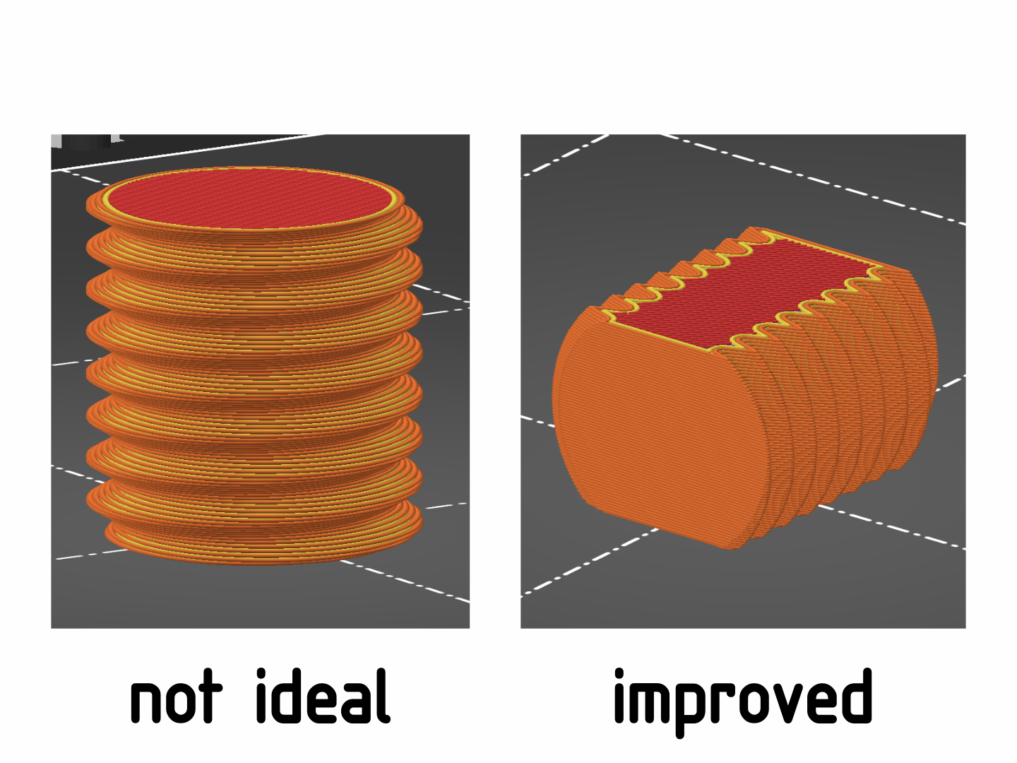
A threaded part designed for upright printing (not ideal for tensile loading) and one designed for printing flat on the bed. By cutting away a part of the thread, it can be printed lying flat on the print bed, without supports.
You should also keep in mind that tensile forces are exerted to some cross section of a part when bending it. This means that you should also align any bending moments parallel to the print surface. A place where this often fails is printed clips, which bend slightly to clip into their counterpart. Such features will break easily when not oriented correctly.
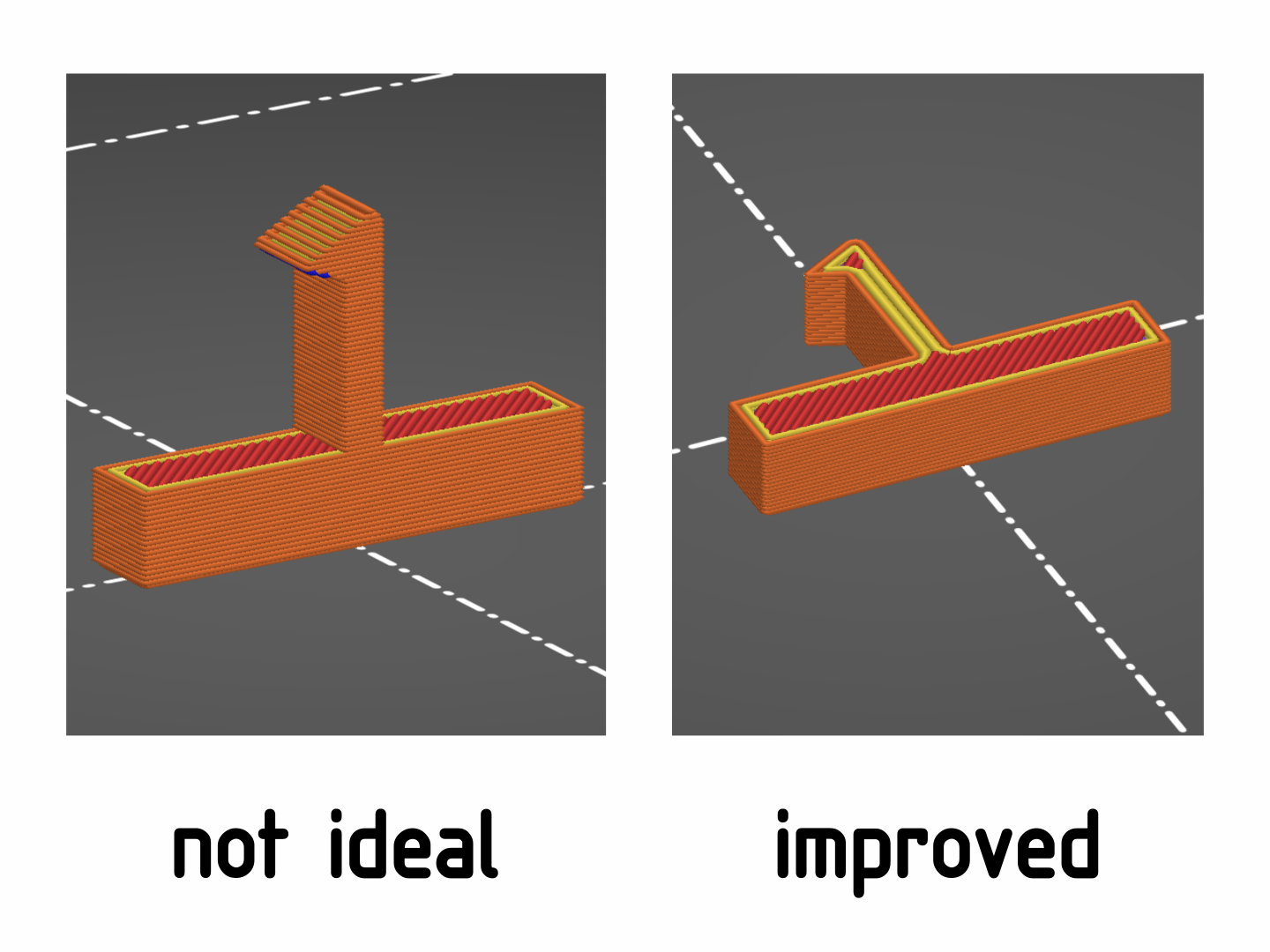
Clips like the one on the left do not survive many uses before breaking.
I also want to give a small tip here about sharing your designs on platforms like Printables: Make sure you upload your models in the correct print orientation. While the correct orientation may seem obvious to you, others might not know and they will try printing your part without reorienting it first. You'll do them a small favor by uploading correctly oriented files 🙂
When no orientation works
Especially with complex parts, in some cases, no print orientation is ideal. While it is often fine to make a trade-off and accept limited strength in certain locations, one alternative should always be kept in mind:
As each piece gets printed individually, you are completely free to choose the optimal orientation for each one. Clever joints can be used to easily assemble the whole part afterwards. Just to mention one: Dovetail joints have proven themselves for 3d-printing, as they are well-printable in most orientations.
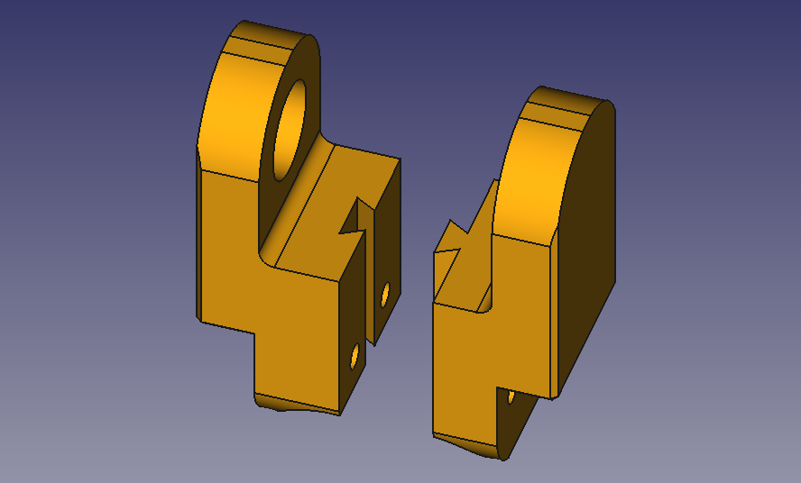
A dovetail joint is used to attach two halves of a part so that each piece can be printed in an improved orientation.
To infill or not to infill
Contrary to the first rule, a topic that is not talked about enough in my eyes is the role of infill in part strength. There is a big misconception that you can magically give your part ultimate strength by just using 100% infill. While you will certainly see an increase in strength, this method is not efficient at all — most of the additional material does not contribute to part strength and is just waste and an unnecessary increase of print time.
Why? It all has to do with the distribution of force inside of a part. Generally, most parts are not stressed in pure tension or compression. Instead, a lot of stress is applied in the form of bending moments and those distribute the force unevenly. The force will be greatest in places furthest away from the center (neutral axis). Thus, it is generally more effective for additional material to be added at the surface, not the center of a part.
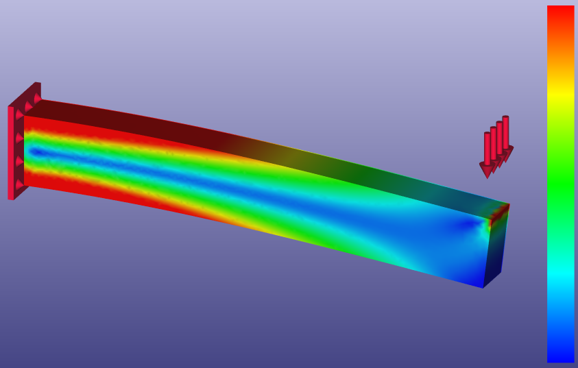
Stress is highest directly beneath the surface of the part. Notice the blue neutral axis in the middle, where stress is lowest.
In 3d-printer speak, this means you should increase the number of perimeters/shells rather than the infill percentage. Stefan from CNC Kitchen has done a thorough analysis of this (YouTube).
In general, his work is a great resource for in-depth information about the mechanical behavior of 3d-printed parts (CNC Kitchen Blog/Website and YouTube).
The Flow of Forces
However, there is more to this. We can actually influence the amount of stress at the surface by changing the shape of the part. This is often much more effective than optimizing print settings. A way to conceptualize the stress inside of a part is to think about the forces "flowing" through it. The visual representation of this is called a force lines drawing (Wikipedia).
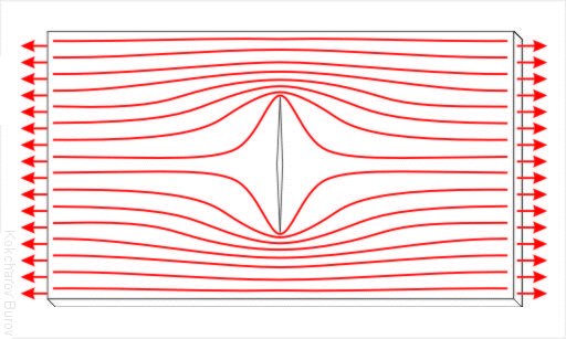
Force lines in a plate with a central crack under tension.
Kokcharov, CC BY 3.0, via Wikimedia Commons
Stress will concentrate in places where the force lines are close together. You can see how the sharp corners of the crack in the image above lead to regions of particularly high stress and thus will probably lead to part failure in these locations.
This isn't specific to 3d-printing but as it is such an important topic, I want to include it here anyway. The rules are generally the same for any manufacturing method: We want to minimize stress and the best way to do it is this:
Or in other words, keep the force lines as short and straight as possible.
One example where this matters a lot are sharp corners. They impact part strength very negatively and are usually easy to avoid by simply adding a fillet. You can see how a fillet allows a much more direct path for the force than a sharp corner:

Force lines around a sharp corner vs. a corner with a fillet.
Cross-sectional Considerations
The inhomogeneous nature of 3d-printed parts with their shell and infill has yet more implications for part strength that are worth talking about. In traditional design engineering, you are taught to reduce cross-sectional area of a part as much as possible. You should only keep material in places where it has the highest effect on increasing part strength. The reason for this is that reduced volume directly leads to reduced material usage and thus cost and weight savings.
With 3d-printing, things work differently. You can usually increase the cross-sectional area quite a bit, without a noticeable increase in material usage, as the infill is mostly empty space. You should rather strive to reduce the surface area of a part, because that is where most material is used.
This means that you can get away with much thicker shapes in 3d-printed parts, which obviously benefits part strength a lot. Don't try to work against this artificially — if a design allows for it, go for the fattest shape possible.
To give an example, think about the traditional I-beam (Wikipedia) cross-section. The idea is that material is only kept in the regions far away from the neutral axis of the bending moment, where it has the highest impact on part strength. This allows for significant weight savings.
While the I-beam profile works wonders for homogeneous materials, it is not a good idea for 3d-printing. A square cross-section of the same outer dimensions will have comparable or better strength but usually does not lead to an increase in material usage and print-time. It might actually perform better in those areas, as shown below.
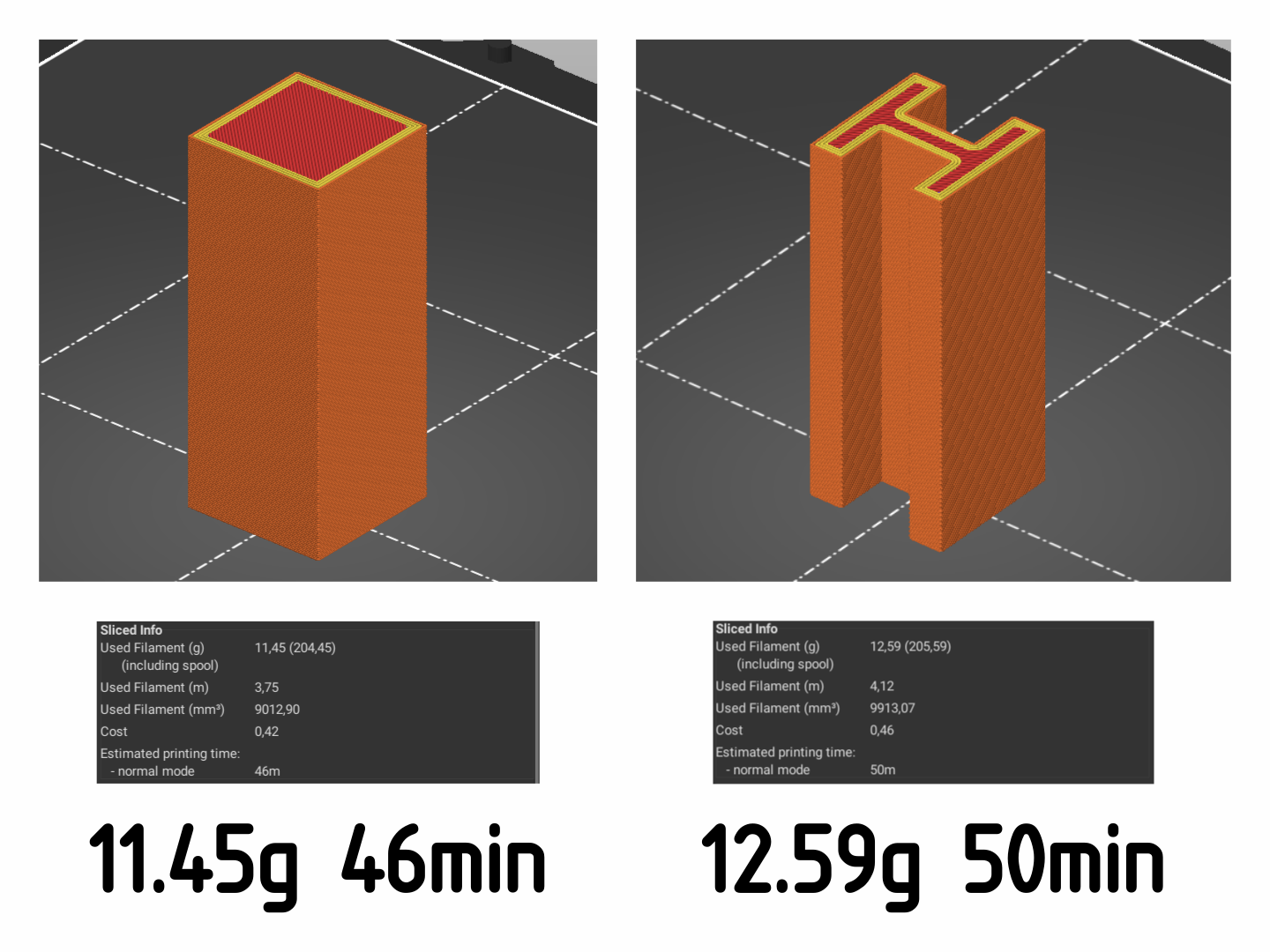
Comparison of print times and material usage for I-beam profile and square profile.
Simulation Struggles
In traditional mechanical engineering, whenever a part needs to be evaluated for its strength, the tool of choice is simulation. Simulation allows making accurate prediction of a part's behavior under load without needing to manufacture it. Especially for parts made from expensive materials or made using expensive manufacturing methods, performing simulations beforehand is critical for the project's budget.
Unfortunately, simulation quickly breaks down when trying to analyze 3d-printed parts. The problem is, once again, the inhomogeneous nature of 3d-printing. While stress analysis may still be useful to find critical areas to give attention to, extracting realistic values for limiting forces is a lost cause.
Luckily, there is an alternative to simulations that 3d-printing offers. The exceptionally low cost of manufacturing 3d-printed parts means that printing prototypes for testing mechanical properties is often the most cost-effective solution. Need to find yield strength of a design? Just print a few copies and empirically determine it.
However, there is one things to be careful with: While I see test-prints as a great way to determine mechanical properties, I advise to not rely on them for determining dimensional accuracy. I will go into more detail on my reasons for this in the next chapter.
Finally, an implication of the above is that topology optimization (Wikipedia) is not really well suited for FFF 3d-printing. While it is amazing for other additive manufacturing processes, current tools are usually not able to produce designs that would truly be optimal for FFF 3d-printing. Not to speak of the often less-than-ideal printability of such parts.
2. Manufacturing Tolerance and Part Finish
Next, I want to talk about optimizing your design to improve manufacturing tolerances. Certain shapes will generally print cleaner than others. If you take this into consideration during design, you can achieve parts that fit on first print and won't need endless tweaking of the slicer settings and printer. A welcome side-effect of improved tolerance is a cleaner part finish as well. Thus, the following chapter covers both: Manufacturing tolerance and part finish.
Chamfers vs. Fillets
To start, let's talk about edges. Generally, mechanical parts should avoid sharp edges because they are unpleasant to touch. Any good design breaks edges by either adding a round fillet or a 45° chamfer of appropriate size.
While the choice between the two is often made for stylistic reasons, there are actually some rather important printability aspects to it. There are two situations that we have to look at, distinguished by the print orientation of the edge:
Adding a fillet or chamfer to edges parallel to the print surface means the feature will be built up from multiple layers, potentially with overhang. Fillets are not well suited for this. They start with an incredibly steep overhang that will not print well. Often, such fillets will have large surface deviations. Even if no overhang is involved, when the fillet sits on top, the changing curvature will make the layer steps very visible, degrading the part finish. Chamfers are much better suited in this orientation. They have a constant overhang angle, leading to a very consistent layer stepping, which looks a lot more pleasing.
Fillets and chamfers on edges parallel to the print surface. The blue perimeter on the bottom of the fillet marks an unsupported overhang.
Contrary, edges vertical to the print surface are much better suited for fillets. A fillet means that the printer does not have to make sharp corners while laying the perimeters. This reduces print-head acceleration and thus reduces surface artifacts (ringing, overshoot). A chamfer on such edges will have two sharp corners, which will never look as pretty and will never achieve the same tolerances as a round fillet.
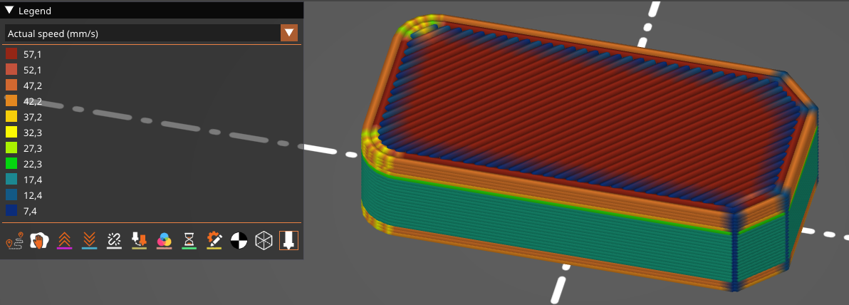
Fillets and chamfers on edges vertical to the print surface. The print speed significantly decreases for the chamfer corners while the fillets can almost keep the same velocity.
Thus, unless stylistic choices dictate something else, the cleanest prints will be achieved by following this rule:
R2.1 — Use chamfers on edges parallel to the print surface. Use fillets on edges vertical to the print surface.
Horizontal Holes
With horizontal fillets, a major problem is the steep overhang. There are other design features where similar problems arise. For example, horizontally oriented circular holes. The larger they get, the bigger the problem will be. The solution is to deviate from the perfect circle for a more optimized shape. For smaller holes, a teardrop shape with a 90° angle works well. Larger holes can be extended to have a flat "roof". Keep in mind that a slight amount of additional clearance will be needed beneath the roof, due to the bridges drooping slightly.
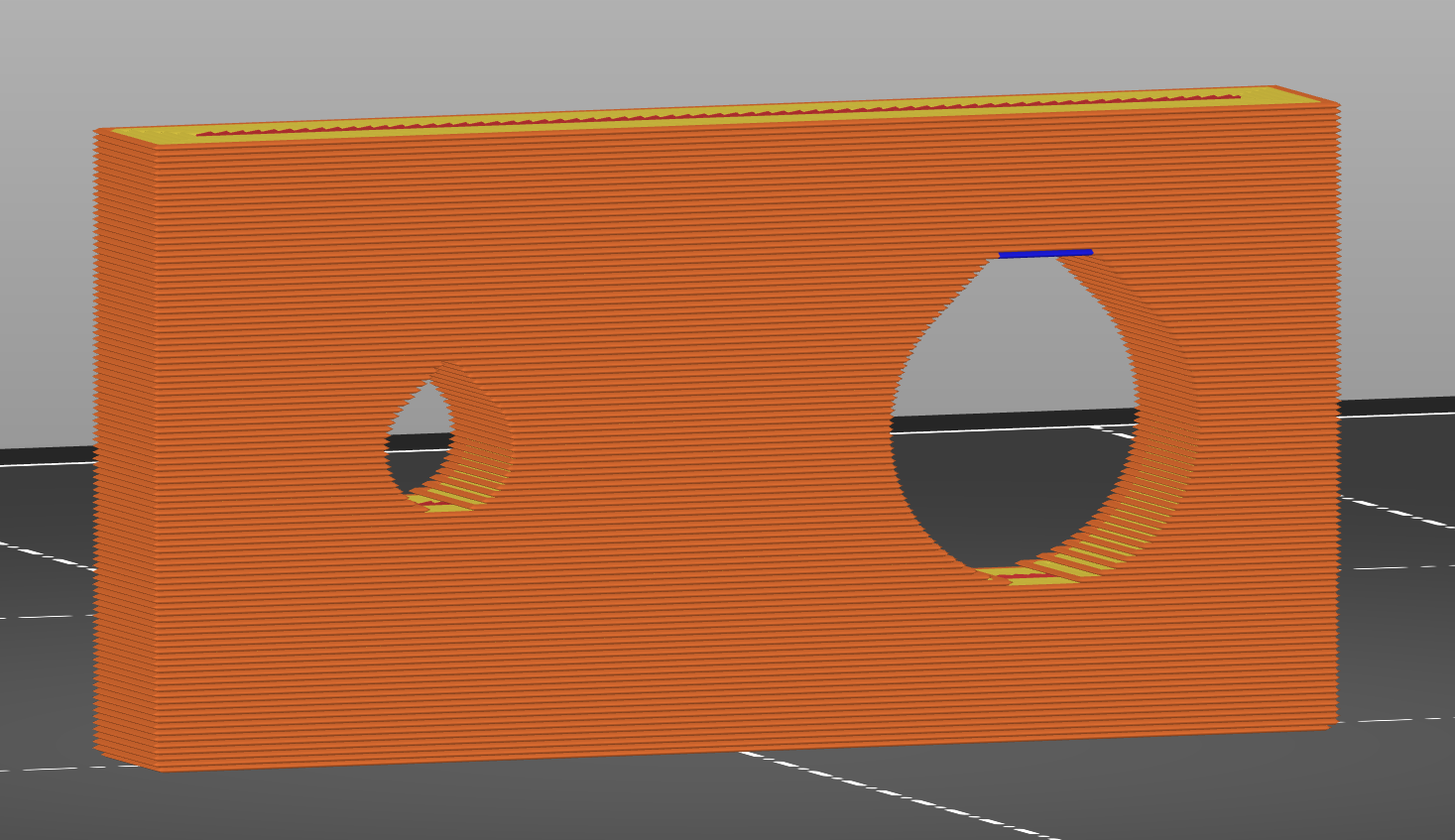
On the left: A ⌀4 mm hole with a 90° teardrop. On the right: A ⌀10 mm hole with a flat roof. The roof sits 0.4 mm above the theoretical circle so slight drooping of the bridge won't affect the fit.
Seemingly Seamless
A topic that is very important for both part finish and dimensional tolerances is the placement of the perimeter seams. Perimeter seams are the point where a perimeter line starts and ends. It is very hard to tune a printer such that there won't be any seam artifacts. Thus, let's put thought into the placement of this seam so it does not interfere with any functionality or aesthetics.
Usually, the seam placement is chosen automatically by the slicer. For each layer, it searches for the sharpest corner (concave or convex) and then places the seam right into it. This has proven to be a very reliable way to produce good results without requiring any explicit user input.
However, this algorithm breaks down in two situations:
- On perfectly round perimeters, like those of a circular hole or outline.
- When all corners have the same angle or when the sharpest corner requires tight tolerances.
Especially the first case is very relevant. This effect has severe consequences for the tolerances you can achieve with a circular hole. While the rest of the perimeter may deviate by less than 0.1 mm, the seam artifacts can easily bump that up to 0.4 mm. And worse, it shifts the centerline of the hole because the seam is only in one place.
The solution is simple: Add a corner where the seam can be placed without interfering. Instead of a perfect circle, shape the hole like a teardrop where the corner has a 120° angle. Note the difference to the horizontal holes discussed previously.
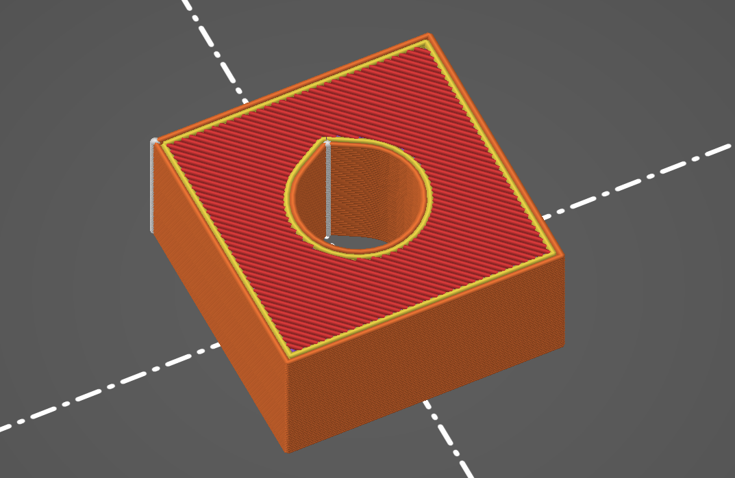
This teardrop shape allows the seam to not interfere with the circular hole (white dots/line indicates seam placement).
Similarly, if other corners must not be used for seam placement, add a small notch somewhere that will serve as the "sharpest corner" and thus take the seam automatically. While you can of course also manually place the seam using the slicer software, this trick means no slicer tweaking is needed.
Difference of forcing the seam placement. On the left, the seam destroys the appearance of the groove in the center. On the right, a small notch on the back of the part takes the seam and the groove looks much better.
To summarize:
R2.4 — Consider where the seam will be placed. If tolerances are tight, provide a sharp concave corner for the seam the hide in.
Expectable Tolerances of FFF/FDM
A fundamental building block of any "design for manufacturing" is knowing the accuracy limits of the manufacturing process. As stated in the beginning, the goal is to build portable designs, so we should assume conservative limits instead of exhausting the capabilities of a particular printer. Note that this is backwards to the traditional workflow: Instead of specifying tolerances that someone else then has to achieve during manufacturing, you accept certain tolerances of the manufacturing process and design accordingly.
It also needs to be noted that a base assumption here is that the 3d-printers in question are well-calibrated. A machine that is out of calibration will have an additional constant error on top of its tolerances. For example, badly configured steps/mm values will lead to a constant factor deviation of measurements along a certain axis. Part design cannot and should not accommodate for this — there wouldn't be much left if we tried.
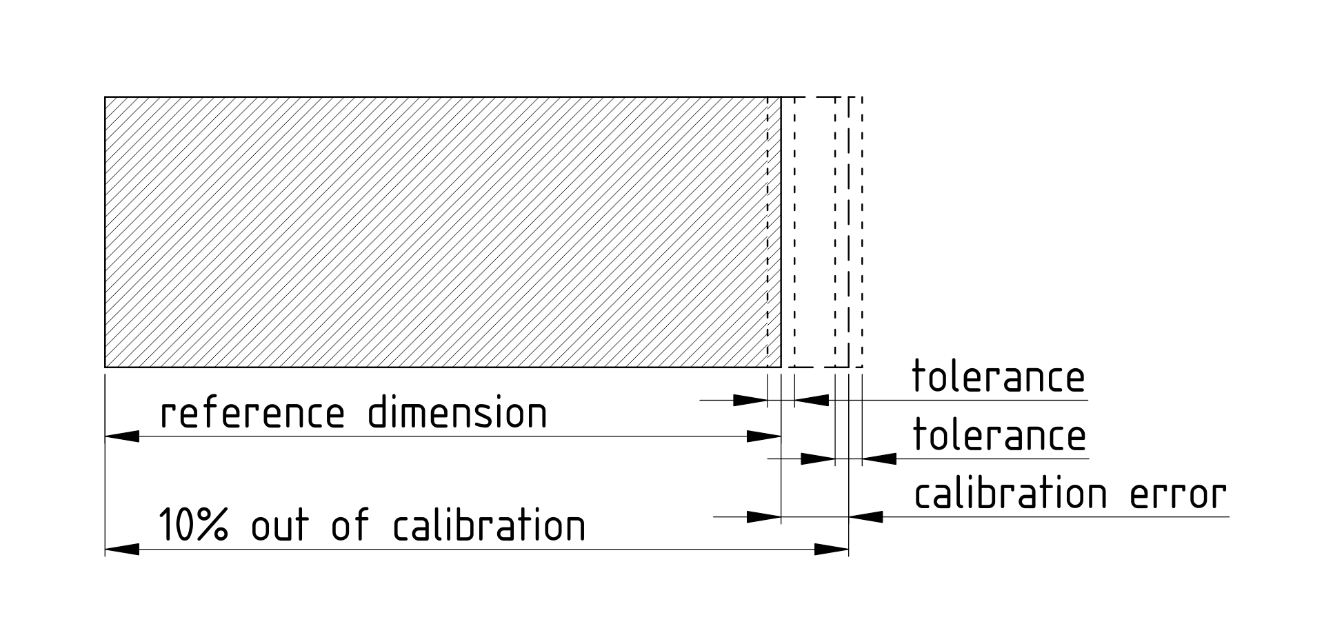
A miscalibrated printer will have a constant error on top of its general manufacturing tolerances.
Before we can talk about tolerance values, it is important to understand what causes these deviations in the first place. A tolerance value means nothing without the context that it applies to. In 3d-printing especially, tolerances will vary widely depending on specific part geometry. This topic is quite far-reaching, as a very large number of factors play into it. As such, this chapter will only contain the most important things to consider.
Starting from the bottom, the lower bound on accuracy is due to the step resolution of the printer's stepper motors and their drivers. Fundamentally, there is no way to get more accurate than this, as dimensions will always fall somewhere between two step locations. However, on state-of-the-art 3d-printers, the theoretical step resolution is around 0.01 mm. Whether this value is actually achievable is debatable, but the takeaway is that step resolution is well below the deviations caused by other effects.
Continuing on, there are more effects of the printer's motion system on dimensional accuracy. They all have to do with mechanical unrigidness of the printer. Tuning the slicer settings and advanced motion control (input shaping) can bring large improvements here. However, an equally big role is played by the geometry the print-head is printing. Sharp corners are the worst offender as they force the printer to maximum acceleration. By optimizing a part for "easy motion", tolerances of printed parts can often be improved a lot.
Once again, fillets and chamfers show quite spectacularly how different the print-head acceleration will be in different scenarios. Sharper corners lead to higher acceleration and will thus have worse tolerance.
The next anti-accuracy component of a 3d-printer is the extruder and hotend. Uneven extrusion makes the line width vary, which has an impact on the outer dimensions of a part. Additionally, the nozzle of the printer always slightly drags the extruded line behind it. This leads to circles always being slightly undersized. On inner circles (vertical holes), assume deviation to make the hole smaller. On outer circles, assume deviation to make the outer diameter smaller, but to a lesser degree.
As a rule of thumb, for current popular FFF 3d-printers with an 0.4 mm nozzle at 0.2 mm layer height, these effects lead to deviations in the range of ±0.1 mm for each surface. The deviations are shifted for circular paths, as mentioned. While many surfaces will be more accurate, this value is a safe bet for surface deviation.
Unfortunately, while 3d-printers usually do not have a noteworthy growth in tolerance for larger dimensions, other effects take over here: Especially warping and shrinkage of the 3d-printed parts as they cool down.
Warping and shrinkage depend heavily on the choice of material, but there are also part geometries that experience it more than others. In general, the more voluminous a part is and the less sharp its edges are, the less warping can be expected. Think about the forces exerted when the material shrinks and how the geometry can resist those forces.
R2.6 — Prevent warping by making parts voluminous and their surfaces smooth and rounded. The ideal shape is a sphere.
Perfect Precision
The previous chapter discussed what tolerances can be expected from the FFF 3d-printing process. However, there are of course situations where more accuracy is required. One approach that is often used to deal with this is experimentally determining a CAD dimension where the final part fits perfectly. 3d-printing makes this very easy because test prints are cheap and fast. Often, 3d-printers have surprisingly good repeatability so a dimension that was optimized using test prints can achieve quite incredible tolerances. Some call this the goldilocks approach (Hackaday).
However, this empirical approach has a huge drawback: It makes your design depend heavily on the slicer settings that were used and the specific printer that the part was printed on. As discussed in the beginning, the goal is to avoid such dependence as it makes the design less portable.
Luckily, there are other approaches that you can use to achieve the same goal, but without requiring tight tolerances. Of course, these approaches also have their limitations. So what is best in a given situation needs to be evaluated on a case-by-case basis.
The first approach I want to discuss here is ingeniously simple. It is best summarized like this (and I wish I had a proper source for this quote):
The idea is that in places where accuracy is needed, you should design your part such that the dimension can be adjusted. There is a huge variety of adjustment mechanisms to choose from. The following four examples should serve to demonstrate the possibilities:
Oblong holes for screws allow sliding a part into alignment. This allows for a large range of motion, but makes adjustments of less than 1 mm very difficult. This method can also be used quite well to correct for angular errors.
An oblong hole is used to allow adjusting the position of a part.
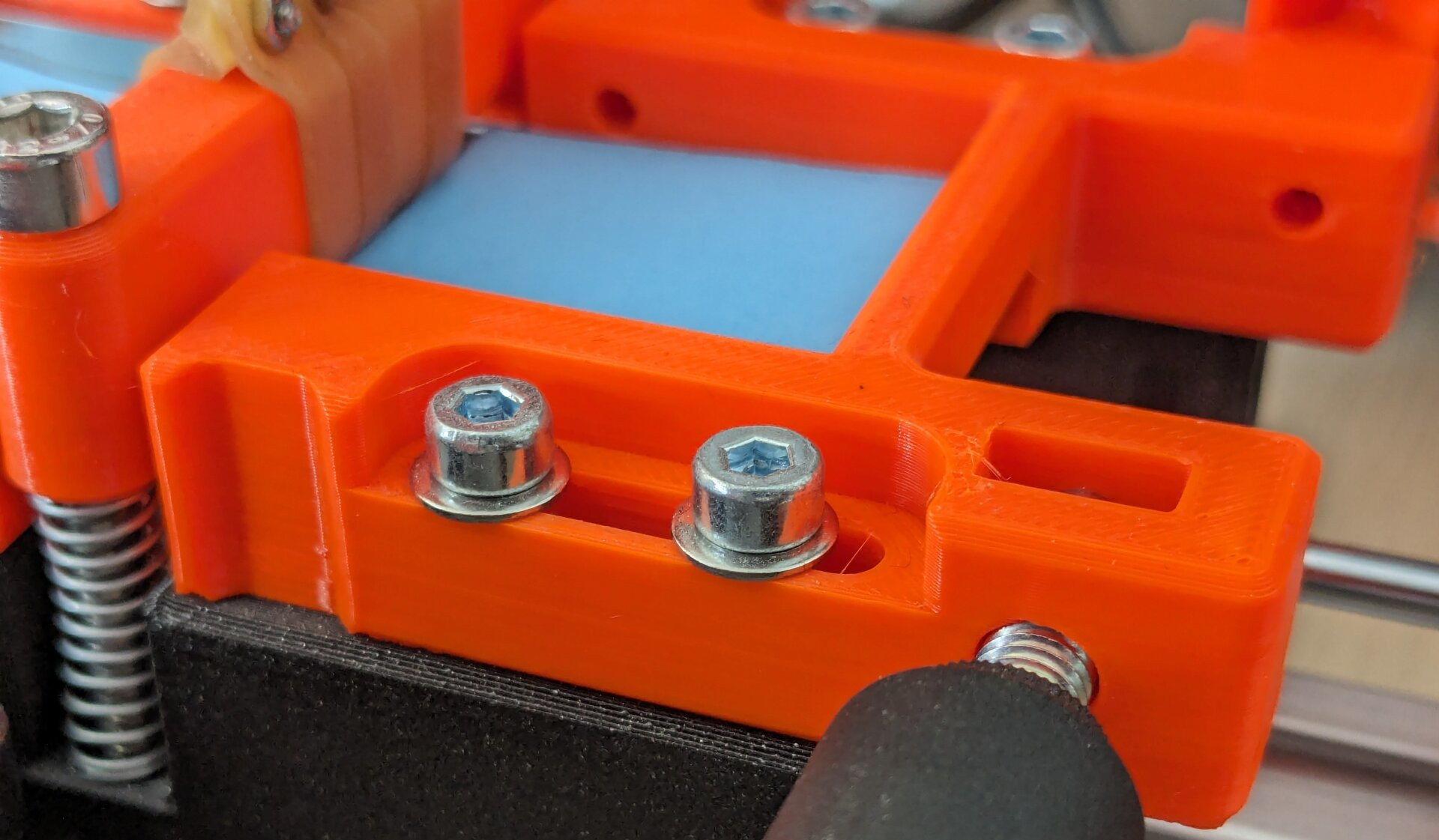
Opposing screws for height adjustment allow fixing a dimension in place quite permanently. The natural reduction of the screws make tiny adjustments easy to perform. A downside is that access from both sides is needed, which is not always easily achievable. Adjusting such a mechanism is unfortunately a bit tedious, because it is a constant back and forth between loosening one screw a bit and then tightening the opposing screw again.
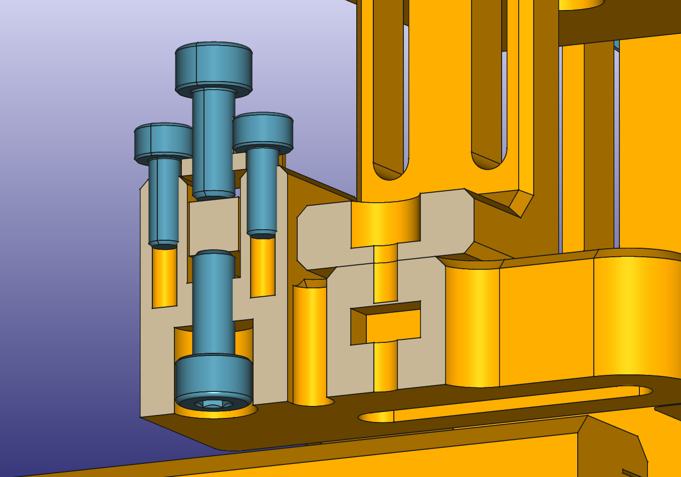
The two screws in the center oppose each other to finely adjust the height of the block between them.
(Grub)screws opposed by a spring or flexure are great for making adjustments very easy. The spring tension counteracting the screw means that turning the screw either direction adjusts the dimension accordingly. If required, a second (grub)screw can be used to fix the part in place after adjusting.
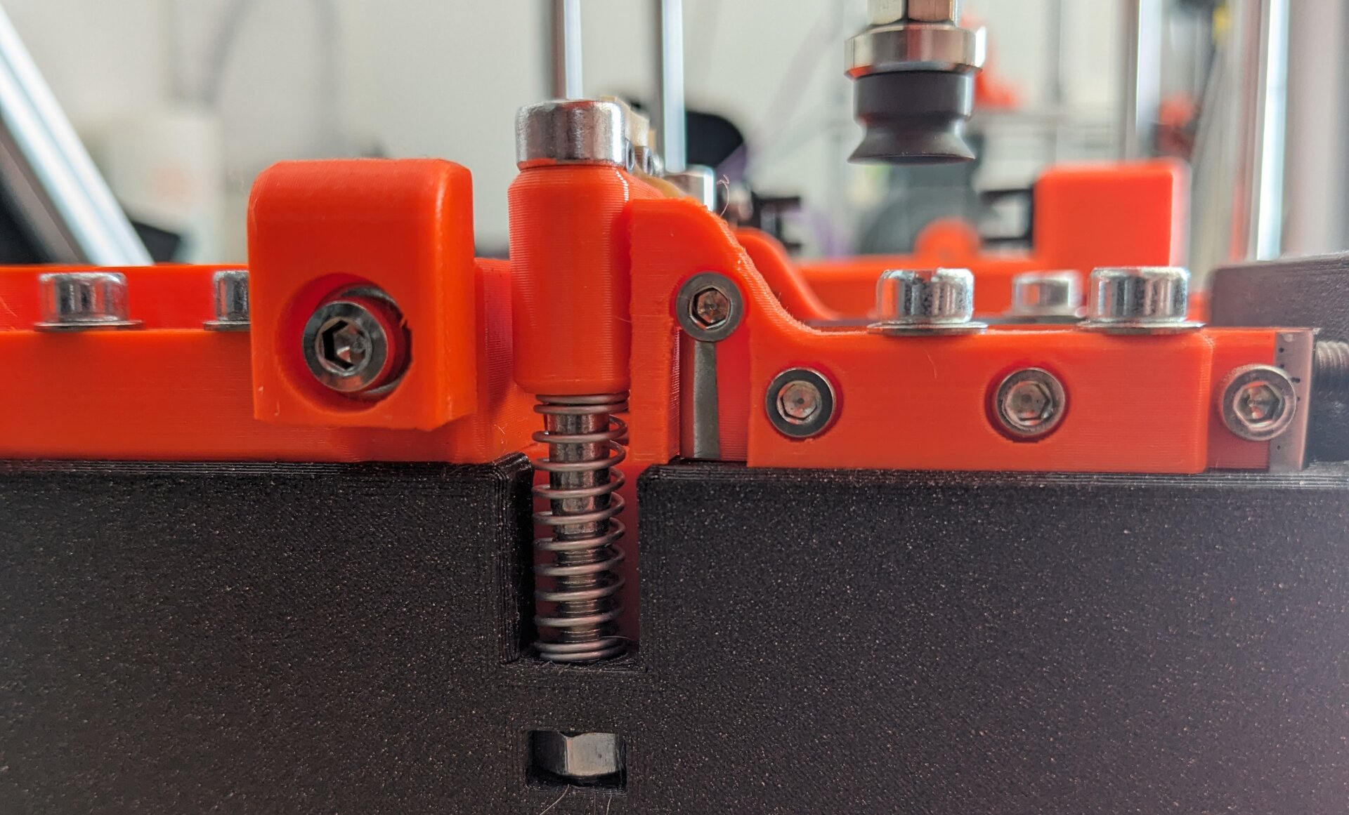
A height adjustment using a long M5 screw opposed by a spring.
Shimming with spring steel shims is the industry favorite for small adjustments that only need to be changed very seldomly. Premade shims in various thicknesses are stacked to achieve the precise offset that is required. Industrial shims are usually made from spring steel, but 3d-printed shims may be conceivable for some applications. However, especially for rather small heights, small surface defects from the printing process could negatively affect accuracy.
Crude example of a small 0.2 mm shim being used for levelling a fixture.
Engineering Fits
In traditional mechanical engineering, when two parts need to fit each other geometrically, a so-called engineering fit is used. An engineering fit is a systematic classification of the allowed dimensions for the two parts. Usually, this system of fits is applied to holes and shafts, but it can be applied to other shapes equally well.
The most important distinction is between
- clearance fits where there is always some play between the parts, for any of the allowed dimensions,
- transition fits where they might be play or interference,
- and interference fits where the two parts will always interfere and thus (significant) force is required to join them. This is also referred to as a press fit.
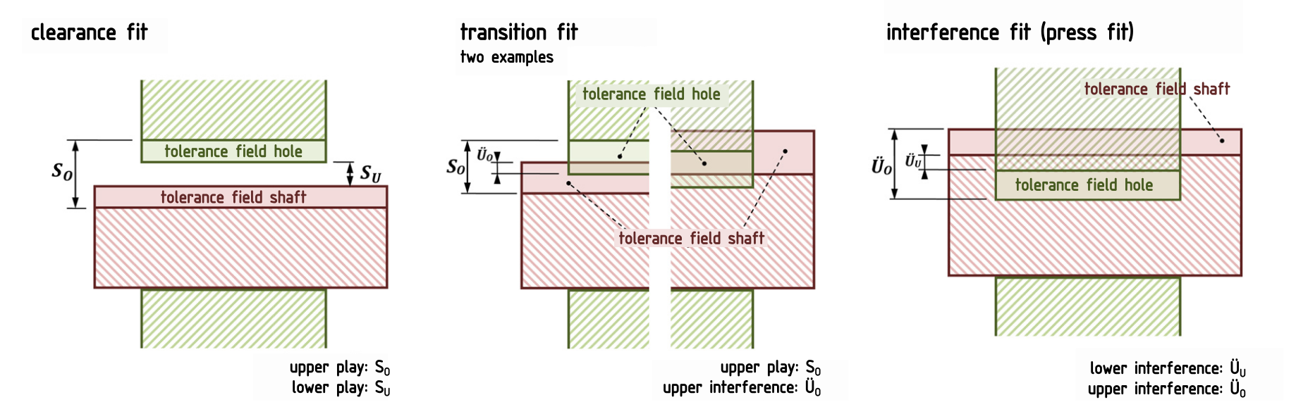
Different types of engineering fits.
ISO 286 then goes on to define specific classes of fits with distinct tolerance bands for the dimensions of the shaft and hole (Wikipedia). These are great for traditional manufacturing, but unfortunately, they are mostly useless for 3d-printing. We can't really print parts to a specific tolerance — instead, the 3d-printer has an inherent tolerance that we have to design for.
If tight tolerance engineering fits are required regardless, an option that should not go unmentioned is post-processing of printed parts. Especially for printed holes, there is the possibility of reaming (Wikipedia) them, to achieve, for example, an H6 fit. That said, this option only makes sense where absolutely required. Otherwise, the additional effort is hard to justify.
For any other cases, the choice is essentially between a clearance fit and an interference fit. Clearance fits are easy — a gap between the parts that is larger than 2x the printer tolerance does the trick. Interference fits, on the other hand, are more difficult. The problem is that large print tolerances mean the forces in the interference fit vary wildly between different parts. In the worst case, this can even lead to joints breaking due to excessive forces.
To counteract this, designs need to tolerate the large tolerances of 3d-printing. There are a few tricks one can use here, which I will share next.
Circles Considered Harmful
The seemingly obvious solution for transition- or interference-fitting a circular shape is a circular hole in your design. However, I want to make the point that this is rarely the best solution for 3d-printing. Especially when the aforementioned tolerance issues become relevant, circular holes should be avoided.
Other shapes, like squares or hexagons can fit the mating part just as well but are much more forgiving in regards to tolerance. The reason for this can be seen when considering how each shape deforms in interference situations. A circle can only widen by stretching along its circumference. This quickly leads to material failure when large amounts of interference need to be compensated. A square or hexagon, on the other hand, can bend to accommodate the bigger diameter. Little to no stretching of the material is present in this case.
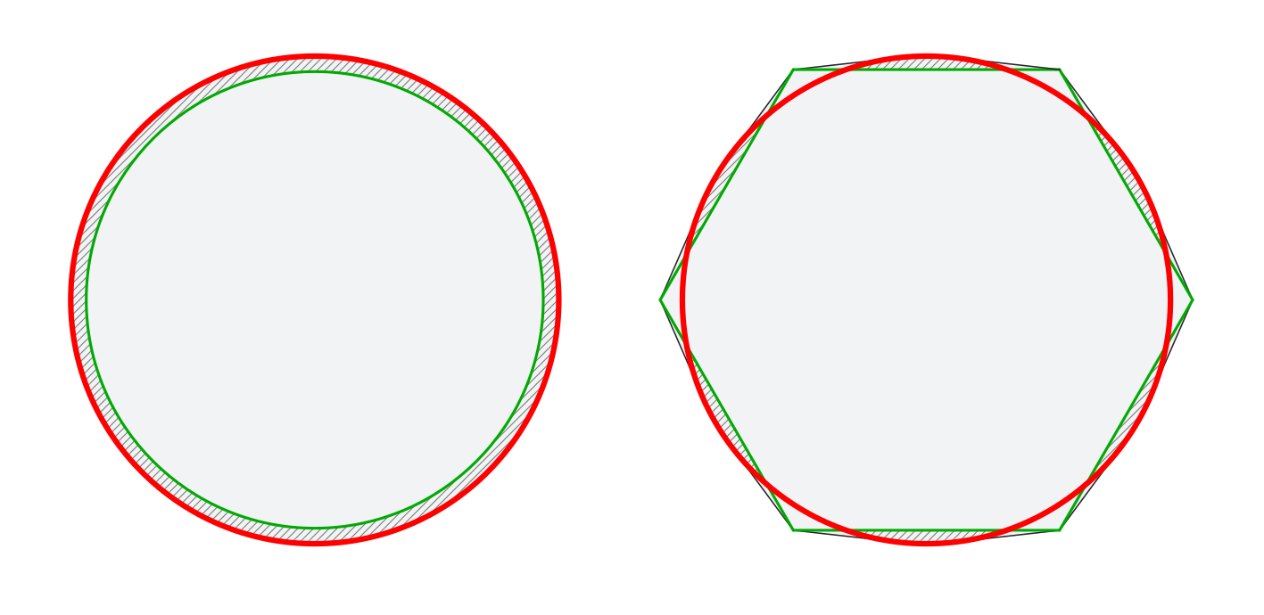
red: oversized shaft / green: undersized circle or hexagon / grey hatching: interference regions
A circle has to stretch significantly while a hexagon just bends a little bit.
Another point in favor or the square or hexagon is the seam problem, as discussed before. A perfect circle will be heavily distorted by the seam while a square can hide the seam neatly in one of its corners.
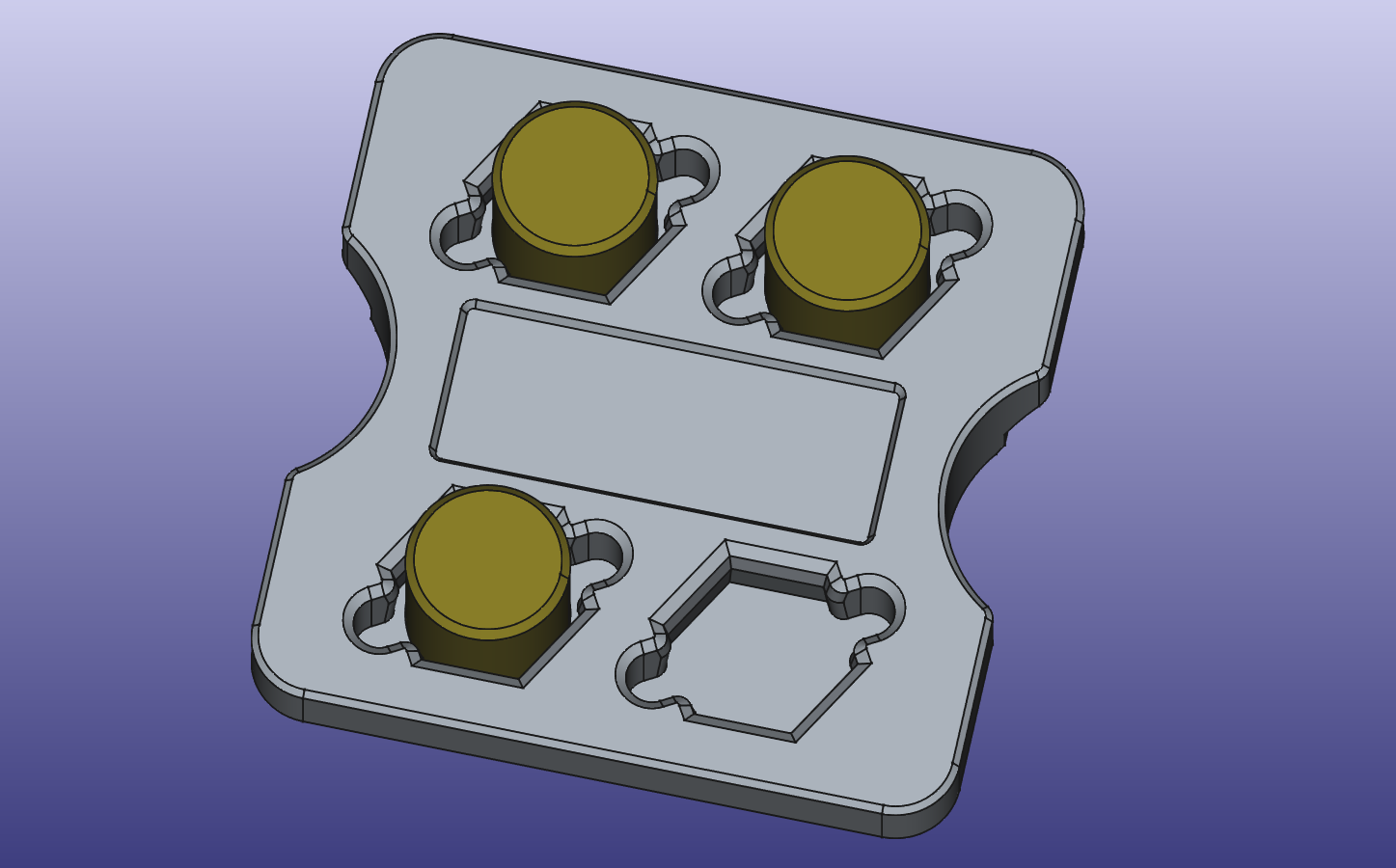
Hexagonal holes are used for a light press-fit with cylindrical stubs. This design also has two pockets to the sides of each stub that help with easy removal.
This technique is mostly useful for smaller diameters. The additional space occupied by the corners can become problematic for lager holes and as such, different design approaches should be preferred.
Crush Ribs
For bigger diameters, there is another trick that can be borrowed from injection molding. Crush ribs are features that are meant to be plastically deformed during assembly. Usually, a ribbing structure is added to a hole where the ribs can be crushed into the "valleys" between them.
In injection molding, these crush ribs are mainly used to work around the required draft angle. For 3d-printing, we can repurpose them to compensate the printer tolerance, as described by Dan Royer (Hackaday).
A blind bore with crush-ribs designed for a press-fit with a shaft.
The ribs are dimensioned such that they still achieve the required interference at either end of the tolerance band. Because deforming the small ribs is much easier than deforming an entire contact surface, the joining force is kept within limits across the entire tolerance band.
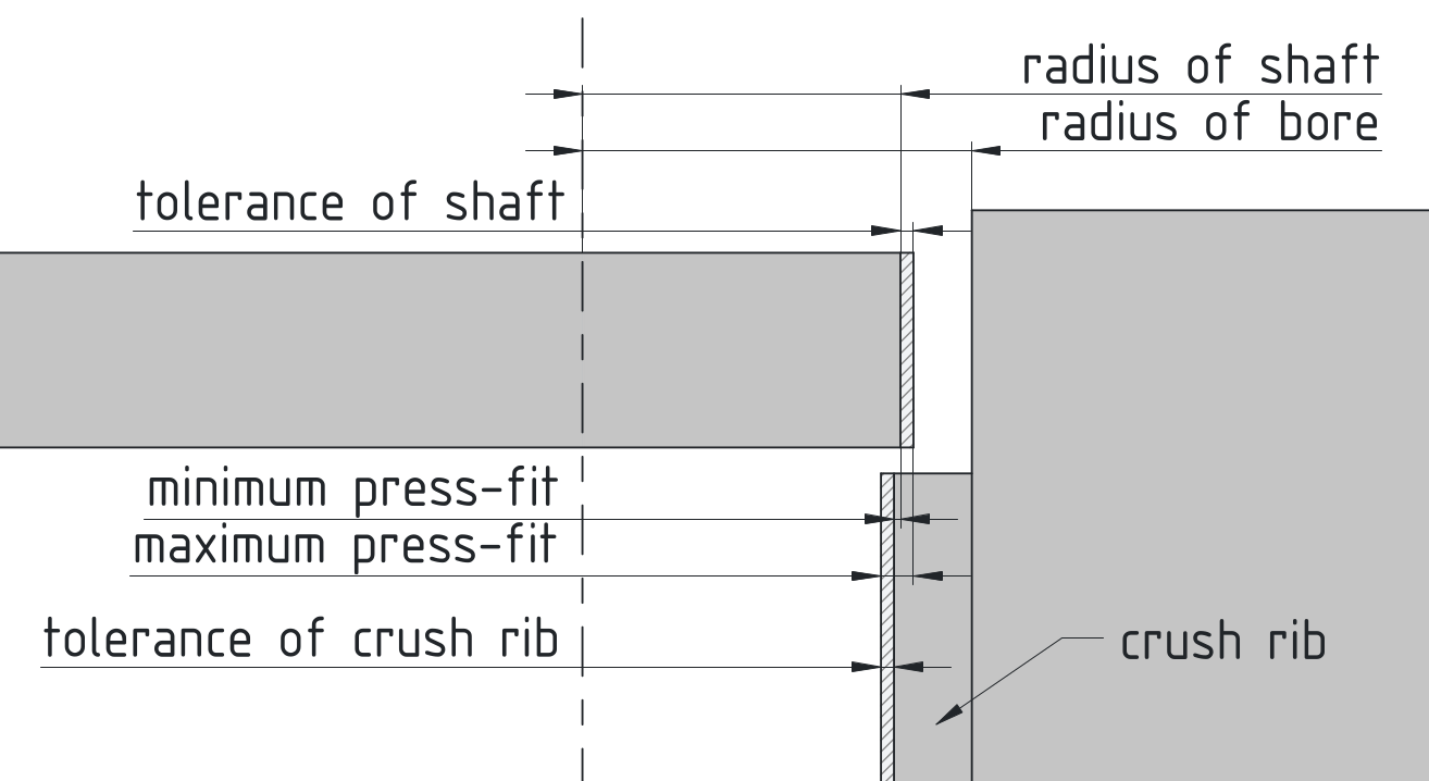
To achieve a secure fit, the force of the minimum and maximum press-fit must be considered.
When designing crush ribs, keep in mind that such small features are prone to have much worse tolerance than larger features. This has two effects:
- The tolerance of the crush rib shown in the drawing above will be larger than usual.
- As the crush-rib is a convex shape, it is likely to be more undersized than oversized.
To give some numbers, undersizing the crush ribs by 0.2 mm and oversizing the bore by 0.4 mm lead to good results for me.
Something to keep in mind with crush ribs is that they should not be reassembled more than once. Their reliance on plastic deformation means that the joint force will significantly decrease on reassembly.
Grip Fins
Another interesting approach presented by Slant 3D is called grip fins (YouTube). Instead of plastic deformation, like with crush ribs, grip fins only deform elastically. The big advantage is of course, that such a joint can be reassembled repeatedly, which crush ribs do not really allow for.
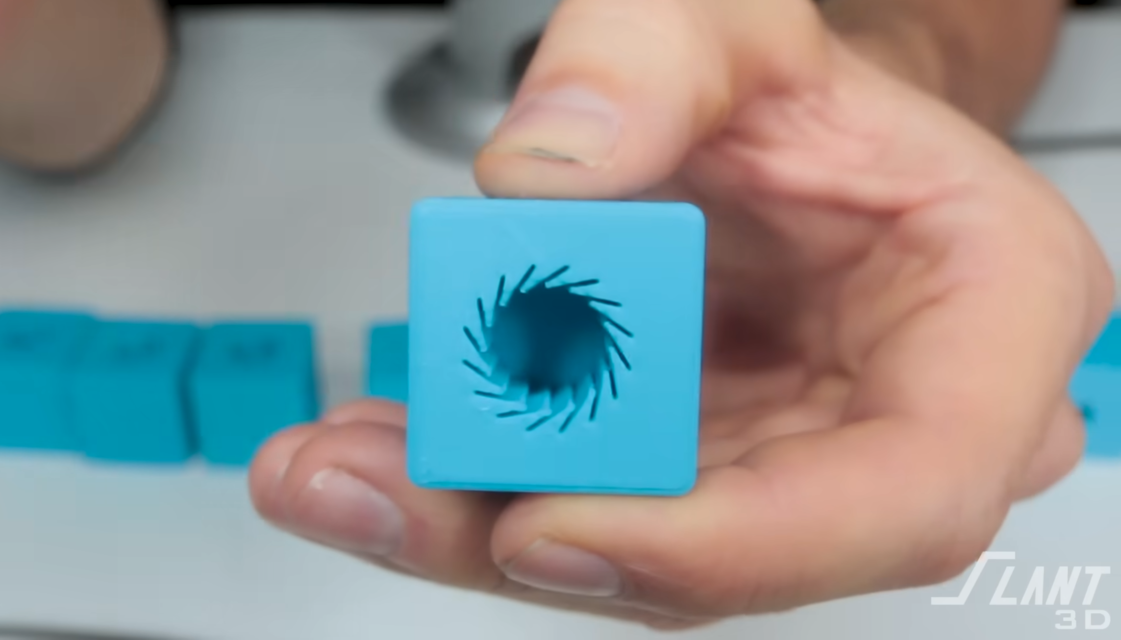
Grip fins are an approach for tolerance compensation that use elastic deformation.
3. Process Optimization
We have talked about designing for strength and designing for accuracy. Let's move closer to the manufacturing process itself. The following chapter will investigate ways to improve parts such that 3d-printing them gets easier, faster, and to make parts less likely to result in failed prints.
Support Material
The elephant in the room is certainly the topic of support material. Support material is used as scaffolding for features of a part that would otherwise hang in thin air. After printing, it is removed, to reveal the final shape.
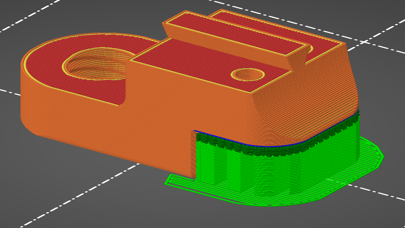
Support material (shown in green) is used to help print an overhang that would not be possible otherwise.
Unfortunately, the use of support material comes with a number of drawbacks:
- It adds an additional post-processing step after printing. The removal of supports can be quite time-consuming.
- It consumes additional material, which later turns to waste.
- It leads to bad tolerances on supported surfaces, much worse than for the rest of the part.
- It leaves a worse surface finish on supported surfaces.
For the designer, the implication is simple:
Yes, there are certainly many situations where using supports is the appropriate choice. But more often than not, slight design changes can eliminate features that would otherwise require supports.
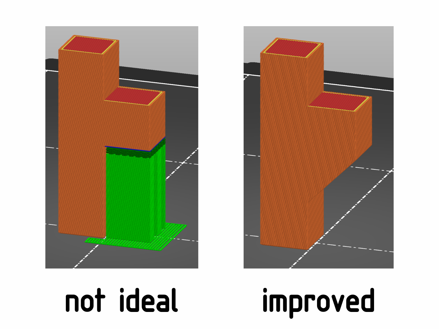
Example of a feature that can be optimized to not require support material.
A big role in this is played by the overall orientation of a part on the print bed. This was discussed previously, for part strength considerations, but has equal effect on support requirement. Balancing between these two is often quite tricky.
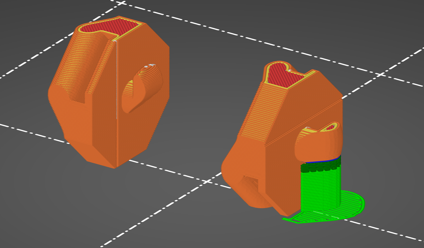
The dilemma of optimizing for part strength or for avoiding supports: The orientation of the hook on the left part needs no supports but the force on the hook can rip the layers apart. The orientation on the right is ideal for strength but needs support material.
In this case, the left option was chosen anyway because the forces are small enough to not break the layers.
One design trick that is surprisingly powerful is the exploitation of diagonal orientation. Rather than keeping the rectangular shapes of a part aligned to the printer axes, tilt the part upwards by 45°.
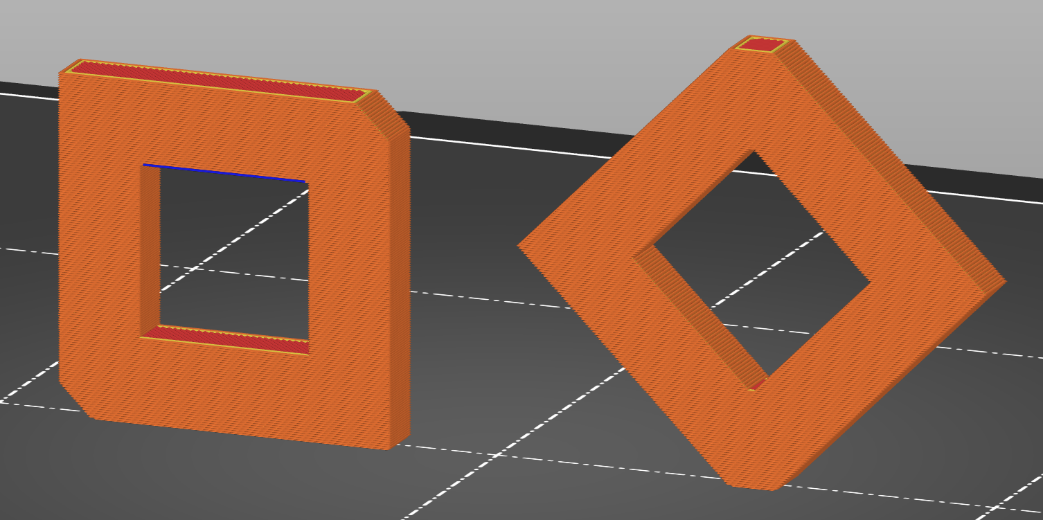
The left orientation leads to a large bridge which will leave inaccuracy and visible artifacts. Simply tilting the part so all the straight edges get printed diagonally leads to all sides getting printed equally well.
Not only does this method avoid supports or overly long bridges, it also leads to a more uniform part finish as all faces now get printed with the same orientation. The easily discernible top and bottom surfaces are elegantly avoided.
Of course print stability is affected by this. You may need to include a brim to keep such parts from falling over. Slant 3D explores this concept of diagonal orientation in more depth (YouTube).
Divide and Conquer
Even with the best intentions, it is not always possible to make a part work without requiring any support material. While this may mean that it is time to accept defeat and just print using supports, there is one last option that should be evaluated. It certainly isn't always the way to go, but it is worth considering:
The trade-off here is between accepting the downsides of support material or making assembly more complex. Both solutions will require some amount of post-print work, but which solution is better will always depend on the exact circumstances. Especially for one-off or low-volume designs, a slightly more complex assembly is easy to justify.
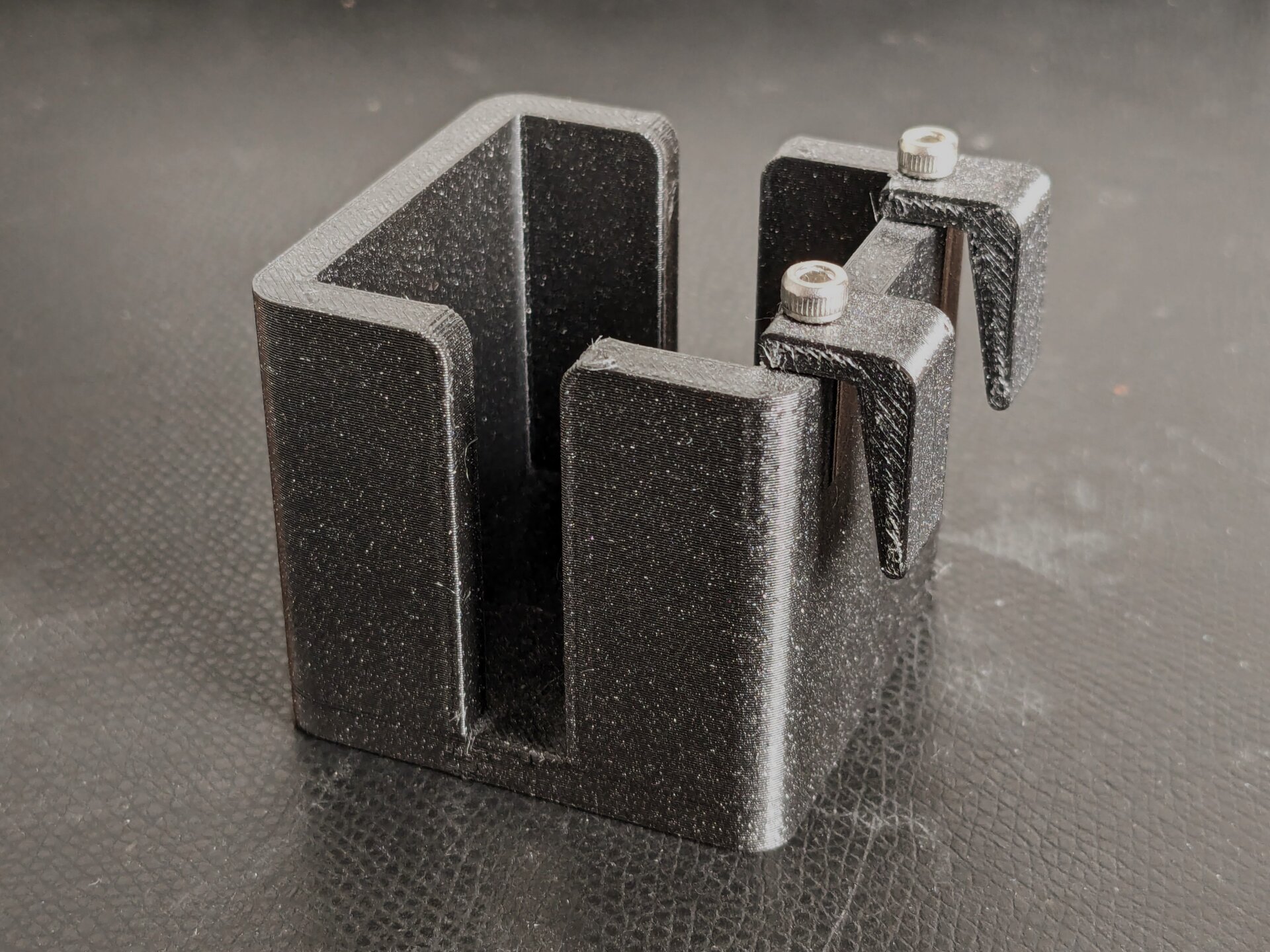
The hooks were printed separately and then attached using screws. This allowed avoiding supports and also helped with optimizing print orientation for better surface finish in critical locations (for example, the taper of the hook).
Sacrificial Layers
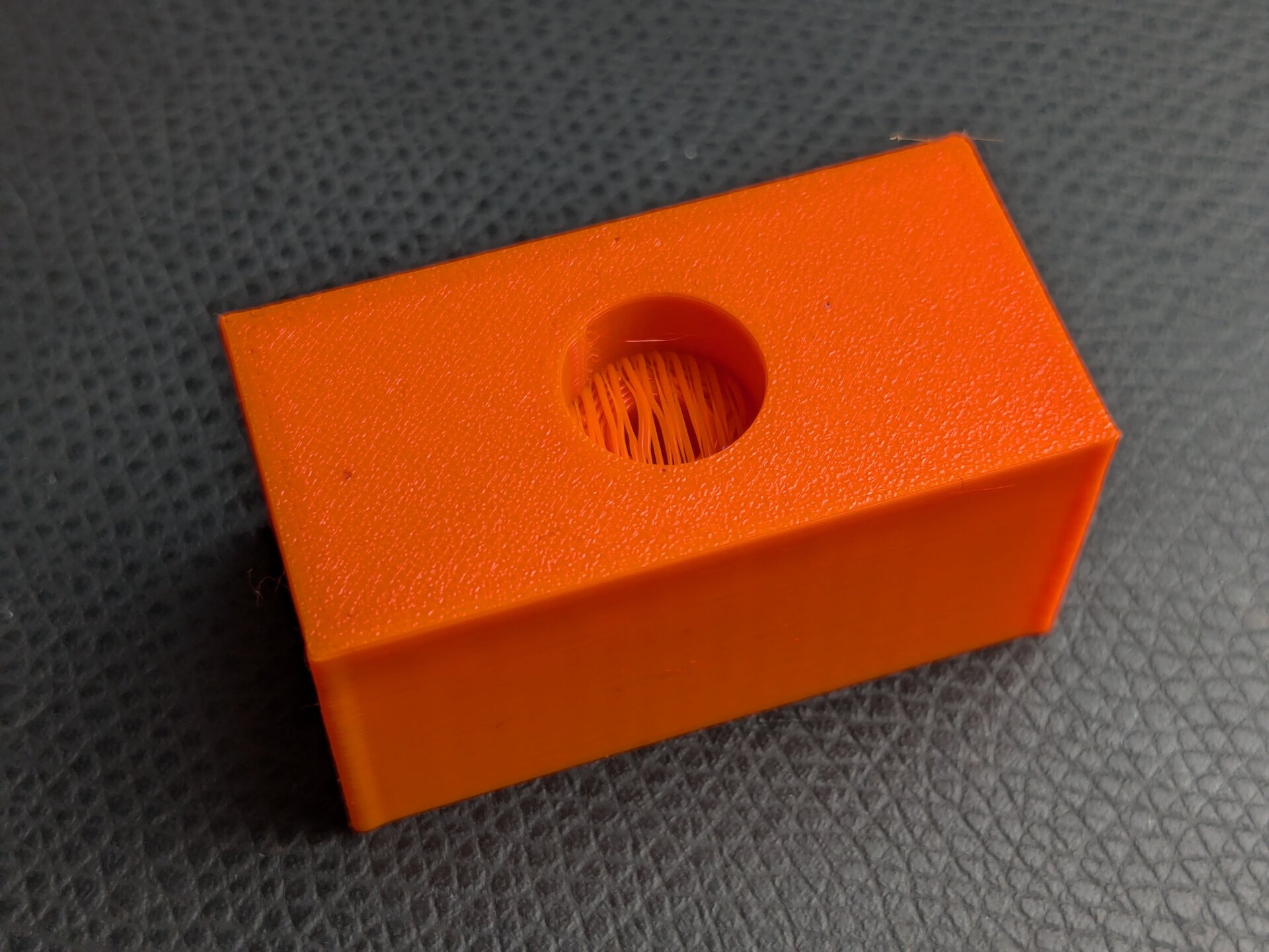
A large number of situations where avoiding supports gets tricky are caused by the need for printing counterbored holes upside-down.
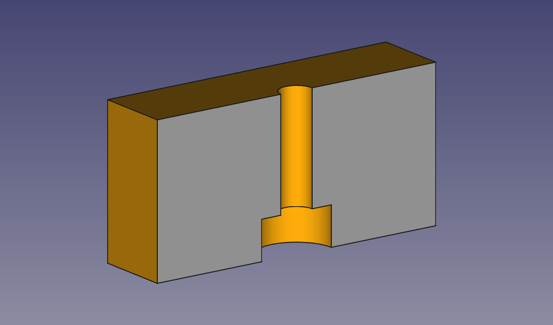
An upside-down counterbore is problematic to print due to unsupported overhangs.
Taking a cross-section, the problem is easily visible: The step of the counterbore is unsupported. Bridges won't work, because the hole in the middle gets in the way. Using support material to help would be particularly nasty here, because removing it from inside the hole can be very difficult.
One solution for this problem is the use of a sacrificial layer. The idea is simple: Instead of an unsupported overhang, a bridge across the entire hole is created. This bridge is only a single layer high and only serves to support the smaller diameter hole on top.

A one layer thick bridge was added to the upside-down counterbore. This layer enables clean printing of the feature and can be removed easily after printing.
After printing, this thin layer is cut or drilled out of the part, leaving behind the desired geometry.
This is what a sacrificial layer looks like right of the print bed. The next step is to cut it out using a knife or to remove it with a drill.
Of course, upside-down counterbores aren't the only place where this trick can be useful. In fact, the next chapter will show an even better solution for upside-down counterbores. But to give an example, I have often used sacrificial layers for the counterbore equivalent of an oblong hole.
The Overhanging Counterbore Trick
Sacrificial layers are a useful tool, but they come with an additional post-processing step. There can also be problems with strands from the bridging becoming loose while cutting out the sacrificial layer. Lucky for us, there is an even more clever way to deal with overhanging counterbores in particular.
Instead of bridging over the entire hole and thus closing the through-hole on top, bridges are only placed where they don't interfere. Layer by layer, more bridges are added to finally achieve the circular inner hole.
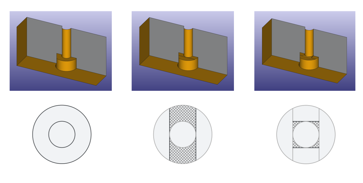
The layers of this design are as follows, from the bottom up:
- First, simply cut the circular counterbore to the desired depth.
- Then, make a one layer thick cut (typically 0.2 mm) such that only material remains where the bridges do not run across the inner hole. Two strips of bridges will be left, running left and right of the inner hole.
- On the next layer, make another one layer thick square cut with the side length matching the inner hole diameter. This will only leave bridges running top and bottom of the inner hole, perpendicular to the bridges on the layer before.
- Finally, from the next layer on, the inner hole will be printed as a circle. This works because the remaining bridges are small enough to not cause issues.
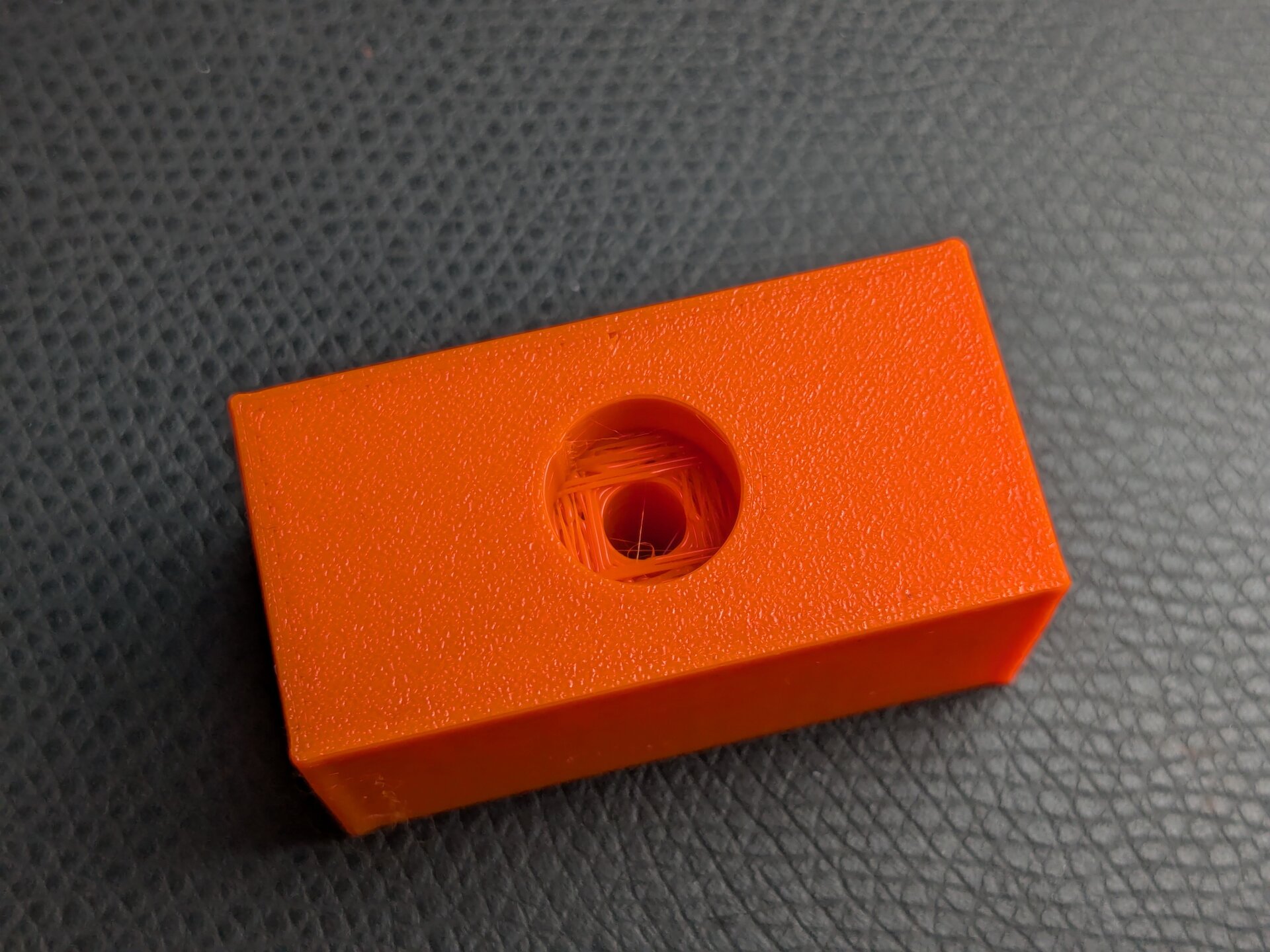
This is what the overhanging counterbore trick looks like from below after printing. You can see the bridges crossing perpendicularly.
This trick is particularly elegant because it does not require any post-processing and it prints exceptionally cleanly. Of course, there is a limit to this, mostly with increasing diameters. But unless there is a good reason against it, this method should be your go-to for any overhanging counterbores.
For transparency, I tried finding an original source for this, but unfortunately it isn't clear who first came up with it...
Layers of Bridges
The concept from the overhanging counterbores can be generalized to an even more powerful method. The basic idea of bridges that support further bridges can be used for quite advanced geometry that does not need any supports. You will also see this called sequential bridging in some places.
An impressive example is the OpenFlexure microscope (Website), where this design approach is used extensively. The best way to understand how it works is to download their models and view the layers after running the model through a slicer (STL Download).
Especially for large bridges, it is a good idea to first build up the bridge for a few layers before starting the next one. This gives the lower bridge more strength and more time to cool before it gets loaded with the features on top.
R3.6 — Bridges on top of other bridges allow for advanced geometry, without requiring additional support structure.
Well Meant Material Saving
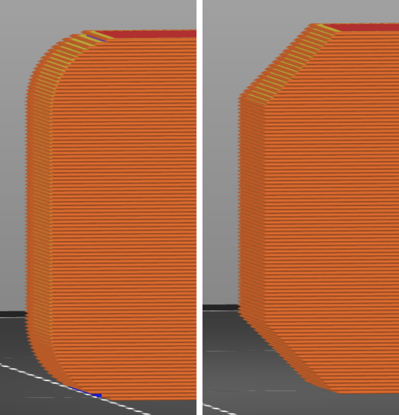
We have previously evaluated the I-beam shape in the context of 3d-printing. The conclusion was that simply shaving off volume is a traditional design approach that does not map well to 3d-printing. There are more cases where this topic pops up. Cutouts, that are meant to save material, are commonly added, while really not achieving their purpose in 3d-printed designs. In fact, they can lead to the opposite: More material usage and longer print times.
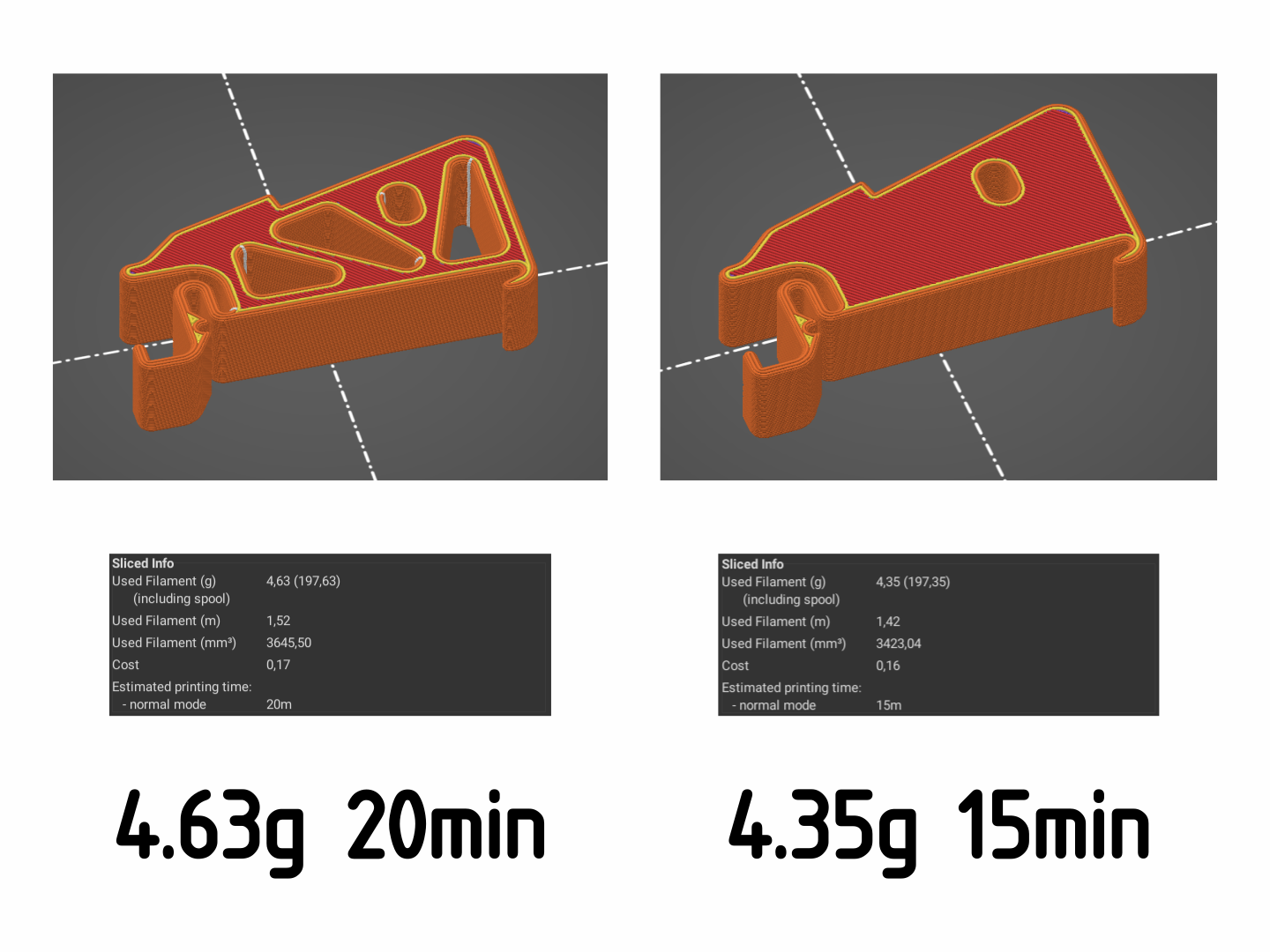
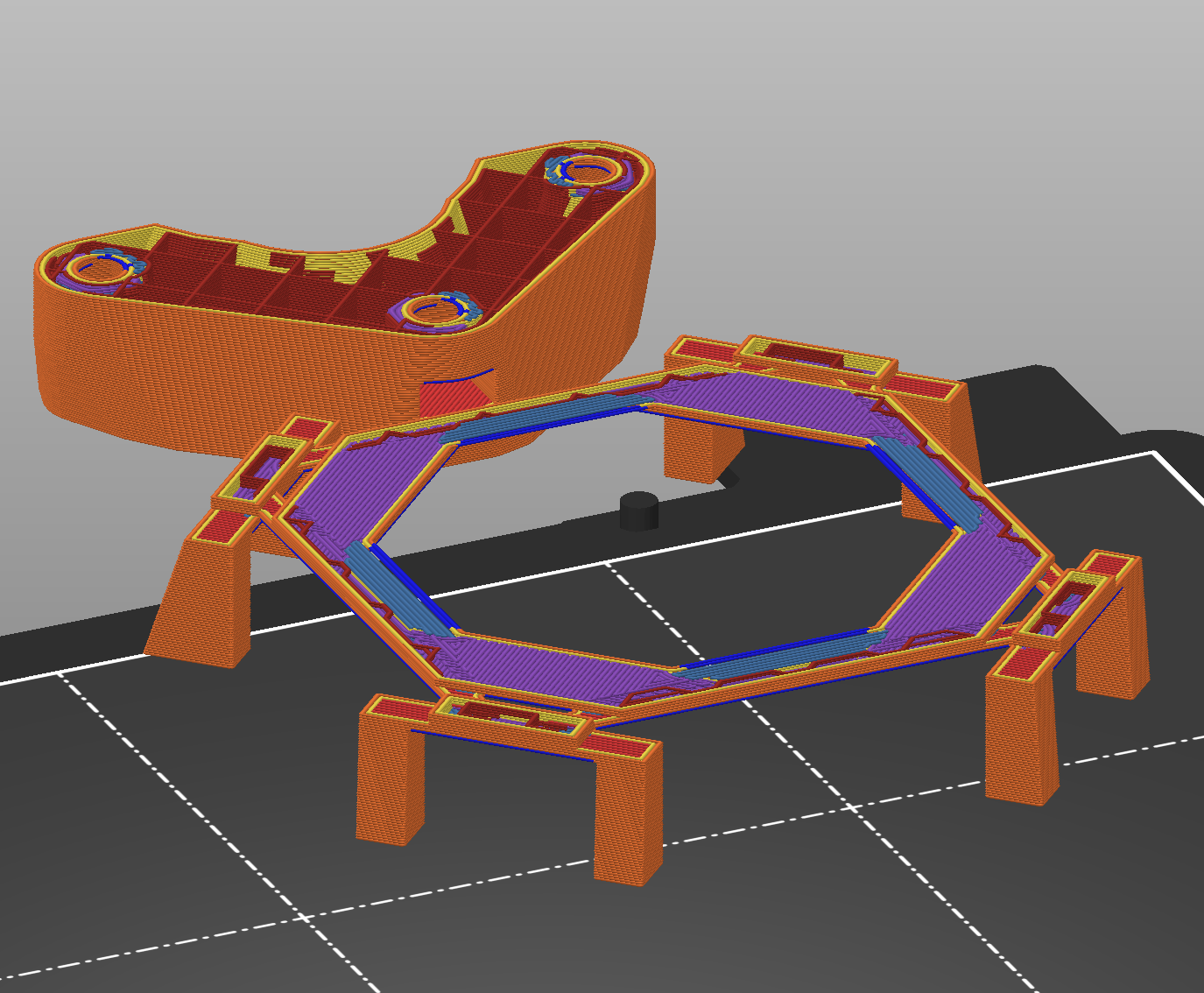
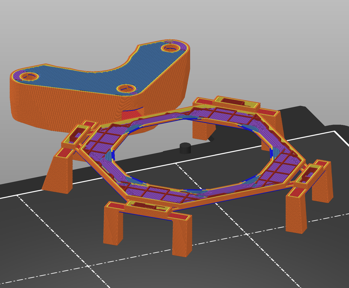
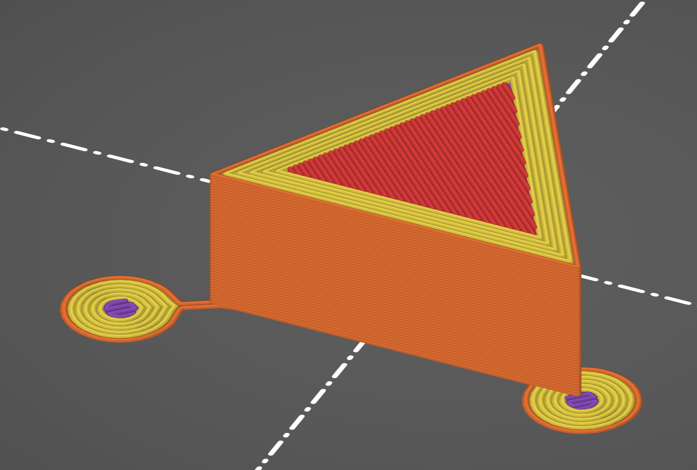
A real world example of a part where holes were added with the intent of saving material. But after comparing the models it gets clear that the holes actually increased the material usage and print time.
It is necessary to shift the focus from volume to surface area, as that is where material is most dense in 3d-printed parts. You should strive to reduce surface area by making shapes fat and voluminous.
R3.7 — Keep surface area minimal. Design voluminous. Do not make cutouts in an attempt to save material.
Optimizing Bed Adhesion
Finally, a topic that mostly becomes relevant when many parts are to be printed. To optimize the removal of the final part from the print surface, certain considerations can be made.
First of all, the surface area that is touching the bed should be carefully balanced. Too little will lead to parts toppling over during printing. Too much will make detaching the part more difficult. Slant 3D has some nice tips about this (YouTube).
Mouse Ears
Related, if you are using brims to counteract parts coming loose, the mouse ear approach presented by Slant 3D (YouTube) is a portable alternative to consider that also reduces post-processing effort.
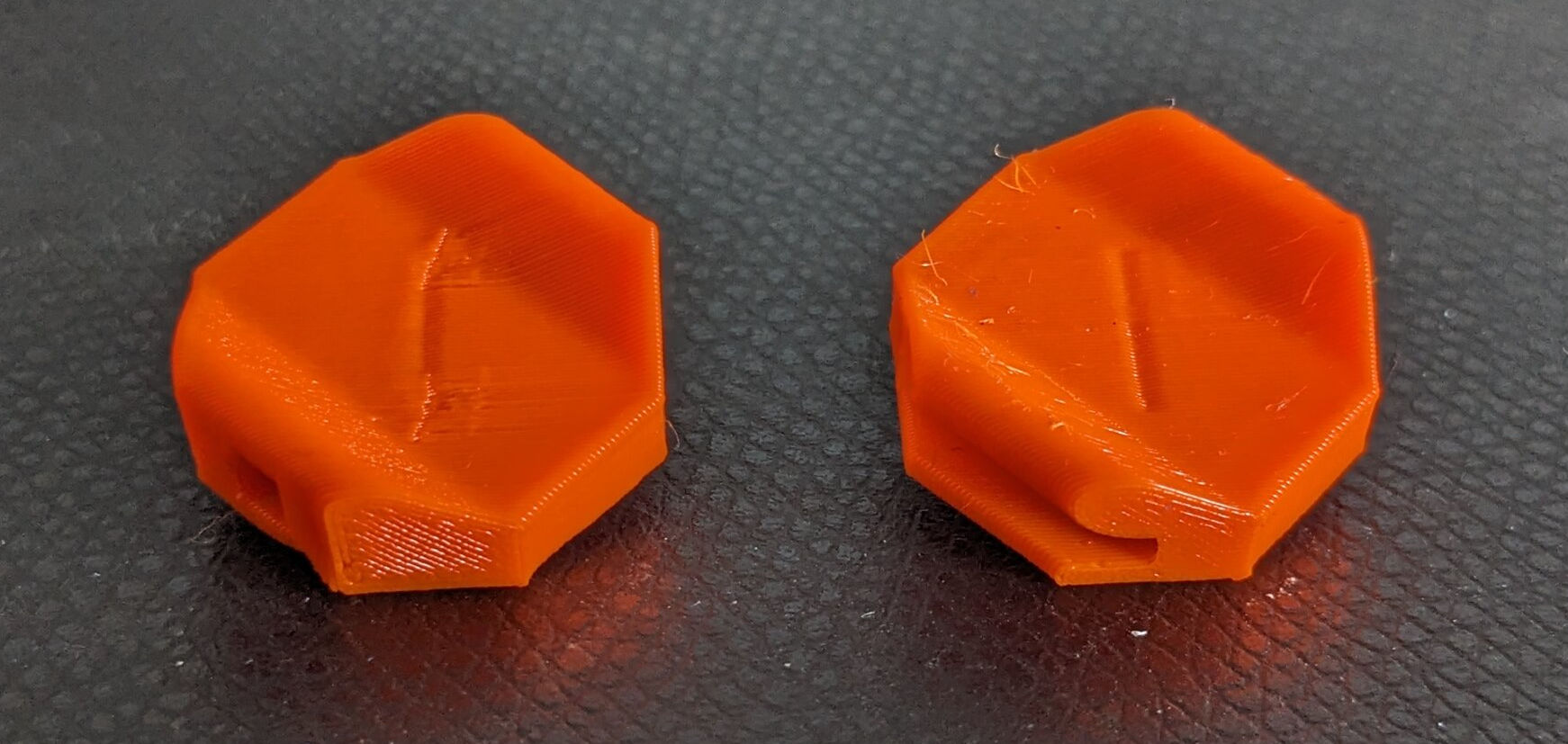
Two types of mouse ears: The right one is placed directly on the part. The left one has a small stub which makes removal even easier.
Mouse ears are directly designed into the CAD shape of the part so they do not need to be added later during slicing.
4. Functional Integration
General Considerations
Functional integration is the art of designing such that each part performs as many of the required functions as possible. The goal is to reduce part count. This speeds up assembly and thus often leads to decreased manufacturing cost.
A ubiquitous example of functional integration are clips in injection molded plastic parts. They replace the additional joining element that would be required otherwise. For this reason, they play a large role in making products cheaper and easier to manufacture. Clips will be discussed in more detail later.
3d-printing is suited especially well for functional integration, because additional geometric complexity does not really impact manufacturing cost. This is in contrast to, for example, subtractive machining, where additional geometric features generally drive up the cost. So striving for maximum functional integration is usually a good idea with 3d-printing.
However, there are some nuances to this. Printing everything in a single part limits the print orientation for some features. This can negatively affect strength, tolerances, and geometric freedom. Additionally, a highly integrated part is more difficult to prototype because each iteration requires reprinting a large model. And later in the life cycle, repair of a broken part also requires replacement of a bigger component than what would have been necessary with a design of many smaller parts that are joined together. More than once, I have explicitly kept certain functions in separated parts to facilitate easier prototyping or repair.
Nevertheless, the following chapters will demonstrate some design ideas that allow integration of certain features.
Zip tie Channels
The first idea that I will demonstrate is a rather simple trick. You can add small channels to surfaces of your part that allow fastening a zip tie to fix some cables or wires in place. There is a great video by Alan Reiner where I learned about this (YouTube). The Zip Tie City demo model is available for download (Printables).
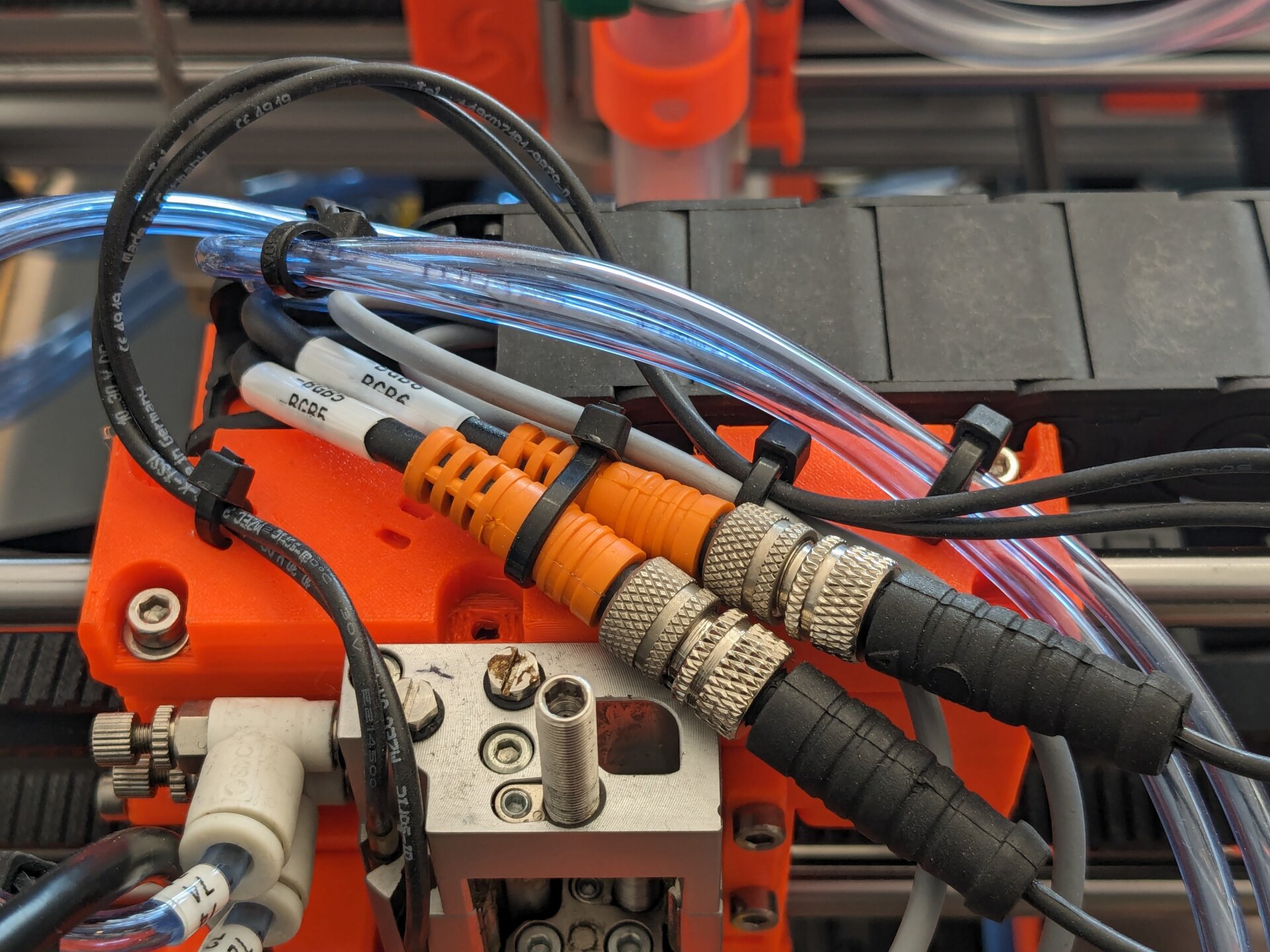
Zip tie channels are used to fix cables to a moving assembly. You can spot one unused zip tie channel to the left.
The channel design is quite simply a section of a hollow cylinder. Dimensions that work well for smaller zip ties (100 mm) can be taken from the drawing below.
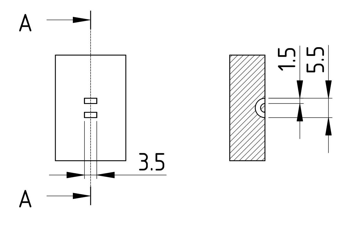
Zip tie channel dimensions for typical 100 mm zip ties.
An important note is that orientation of the zip tie channels should be considered. When the channel is printed such that no perimeters bridge across it, it gets much weaker. In this orientation, the bridge can easily get ripped out which I have already seen happening in practice.
Flexures
Usually, mechanical parts are designed such that they can be considered completely stiff in approximation. Flexures are design features that explicitly use elasticity of a part to integrate certain freedoms of movement (Wikipedia).
Overall, 3d-printing is perfect for designs that incorporate flexures. The thin features required by flexures are easy to print, while complex to create with other manufacturing methods.
Two types of flexures that are very common will be discussed in more detail below: Clips and so-called "living hinges". But first, a few general points about flexures in 3d-printing are presented.
The amount of movement allowed by a flexure is mostly limited by how much deflection is possible without plastic deformation. A thicker flexure will start plastically deforming much earlier. Thus, it is very important to keep flexures as thin as possible when large movements are intended. Force can be increased by stacking multiple thin flexures, rather than creating a single thick one. Alternatively, the travel distance of a thicker flexure can be increased by increasing its length — maybe even in a snaking pattern.
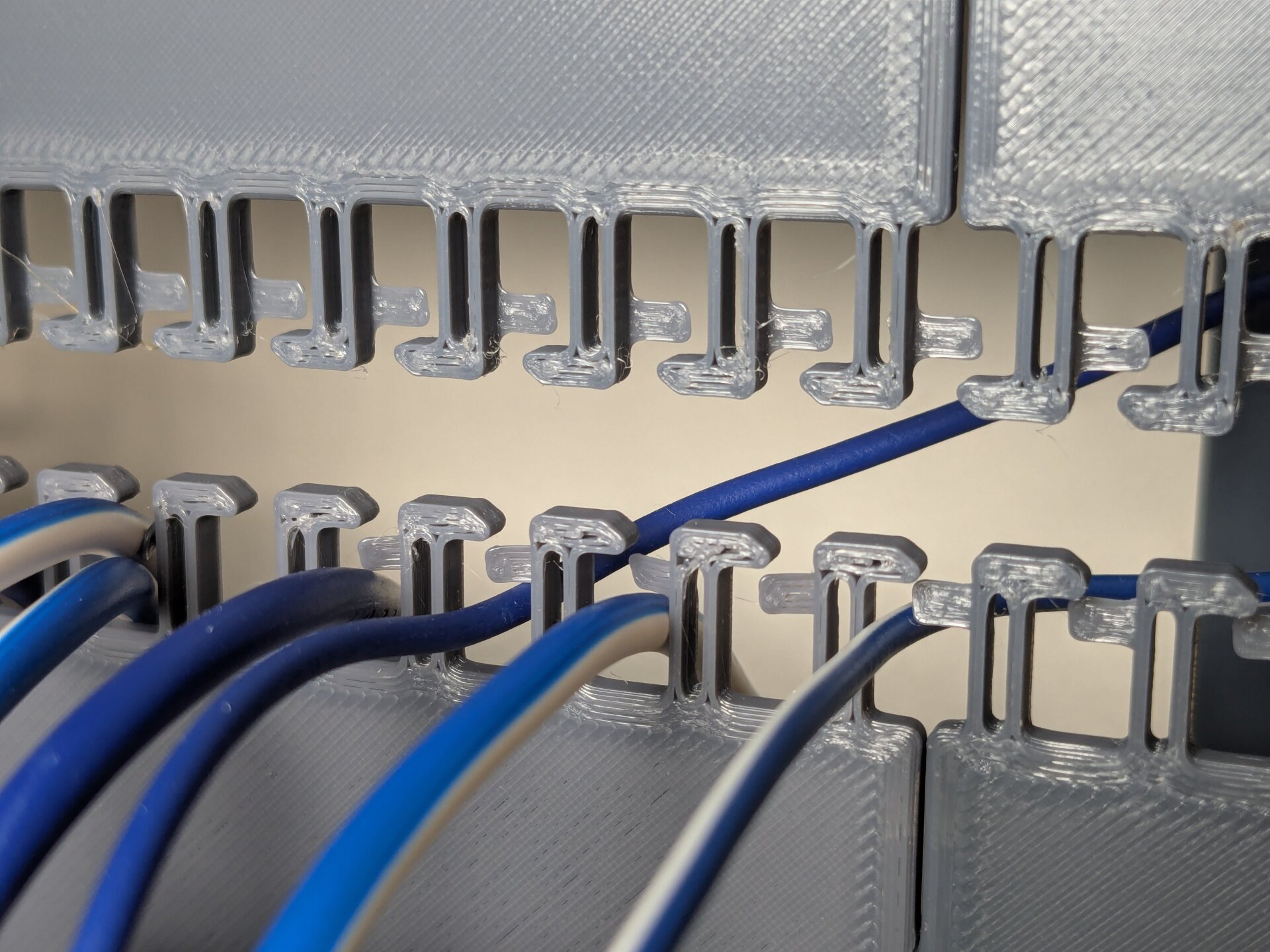
The hooks on this cable comb are made from two parallel flexures. This is more stiff than a single flexure, but has the same travel in the elastic region.
To make flexures long-lived, it is important to ensure they cannot be moved too far. Features should be strategically placed as end-stops to a flexures movement. This way, the movement is always kept in the elastic region and the flexure will live much longer.
Another use for flexures is sidestepping tolerance issues. This only works when no significant force is exerted on the joint, but can be a nice tool to cheaply solve accuracy issues. An example of this are the previously discussed "grip fins".
Clips
Arguably the largest amount of flexures show up in the form of clips. Clips have revolutionized the mass-production industry because they provide a fastener-free way of joining together parts. Either permanently or in a way that can be repeatedly opened and closed again. For the same reason, clips are popular for 3d-printed designs — avoiding additional fastening hardware is often desirable.
However, care must exercised with design of clips. The travel distance of the clip, retention force, and feature size must be carefully balanced. Another significant factor is the orientation of the clip relative to the print surface. Especially clips built across layers are very fragile. In many cases it is better to keep travel minimal and instead work with a larger clip force for retention.
For clips that retain by form-locking the other part geometrically, it is a great idea to include a way to undo the clip. Usually, this can be achieved by providing space to reach the clip with a tool like a screw-driver to push it backwards.
Living Hinges
One more type of flexure that has exploded in popularity as part of optimizing for mass-production are "living hinges". These are hinges which move by plastic deformation rather than disjoint parts rotating on an axis. Any cheap plastic container with a lid probably uses one or two of these hinges, because they are so much more cost-effective and simple than proper hinged joints.
We can also make use of living hinges in 3d-printed design, but there are a few limitations: The hinge absolutely needs to to lie flat on the print bed to achieve the thin sheet of plastic that reliably deforms. Experiments have been done with living hinges made from bridging layers, but these do not perform nearly as good.
Example of a box with a large living hinge by @3DMakerNoob.
Engineers Grow has discussed living hinges for 3d-printing (YouTube) and so has Slant 3D (YouTube).
Printed Bearings
Another design element that's sometimes suited for integration are bearings. Especially where large diameter bearings are required, it can be more effective to integrate the bearing into the design of the mating parts instead of using an off-the-shelf component.
To integrate a bearing, the races become features of the part design. During assembly, standard steel bearing balls are inserted. Optionally, a printed cage may be necessary to ensure correct spacing between the balls.
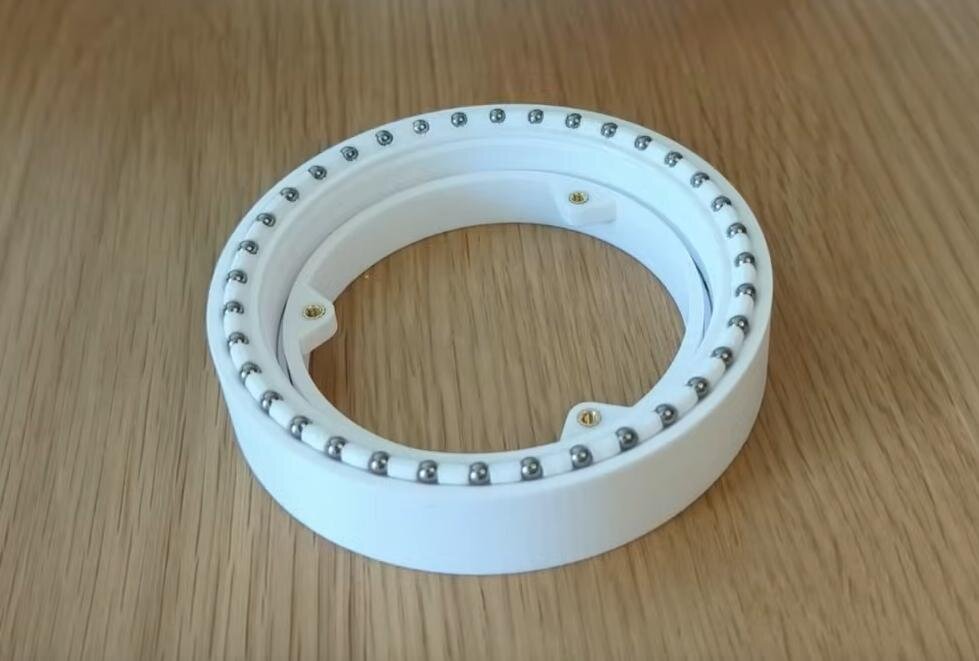
Example of a 3d-printed bearing by Positive Altitude.
Positive Altitude has published a video where printed bearing design is discussed in a lot more detail (YouTube).
Print-in-place Mechanisms
As the final type of functional integration that will be discussed, print-in-place mechanisms are another unique possibility of 3d-printing. Multiple parts of an interlocking mechanism can be printed at the same time. No post-print assembly is required.
Print-in-place mechanisms can include joints that would be impossible to assemble after printing. The trick is that interlocking parts are printed in their already joined position. This can be an incredibly useful design tool to make strong mechanisms without complicated assembly.
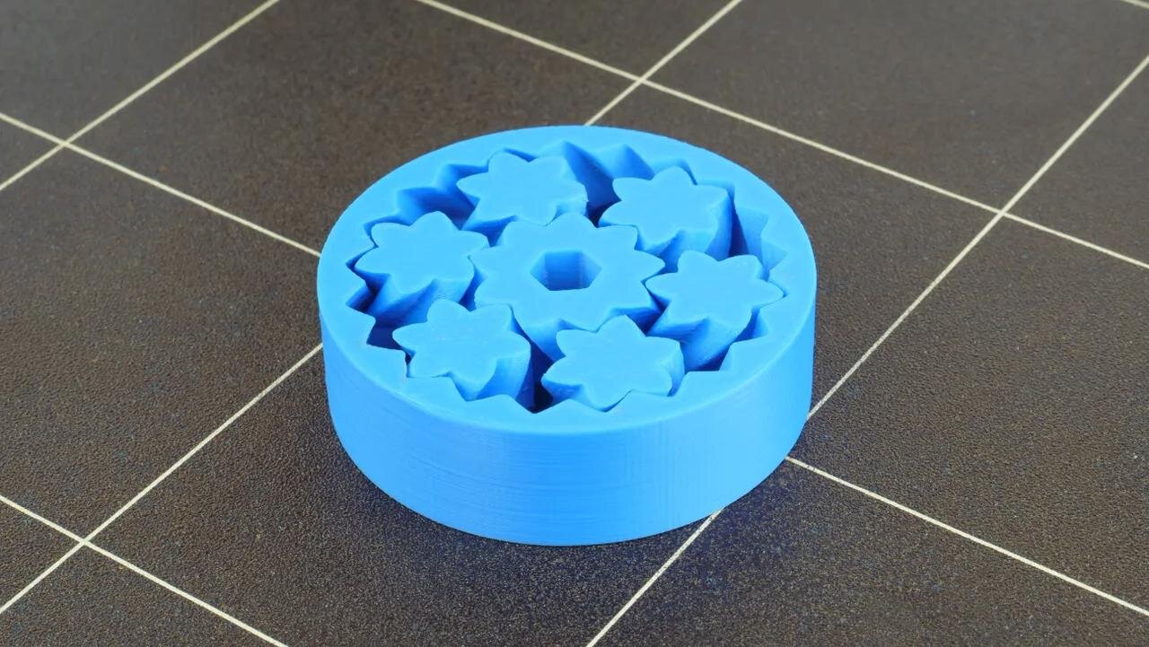
Standard example of a print-in-place mechanism is the herringbone planetary gear set. This model could not be assembled from its parts after printing.
Design by Emmett Lalish and picture by Prusa Research.
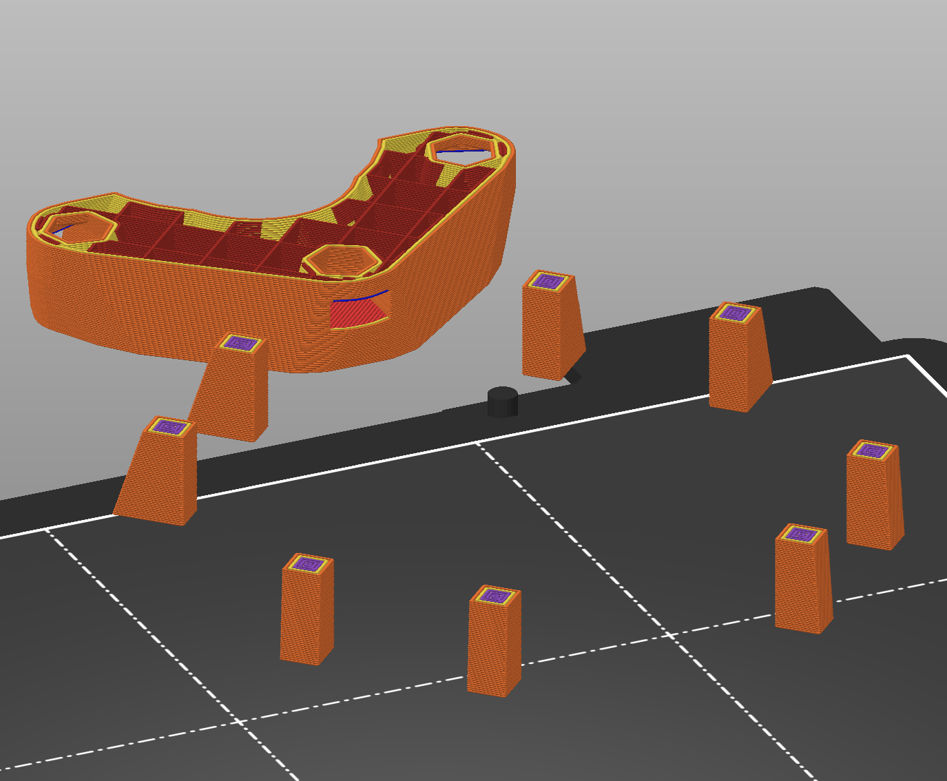
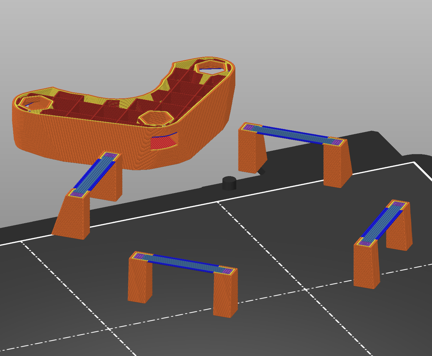
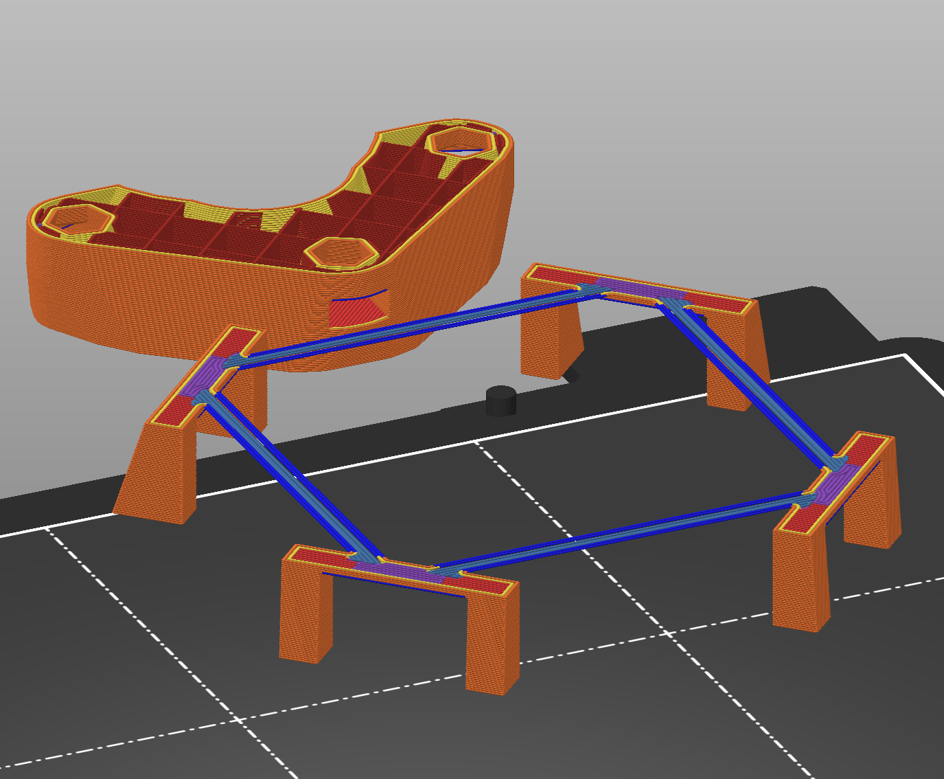
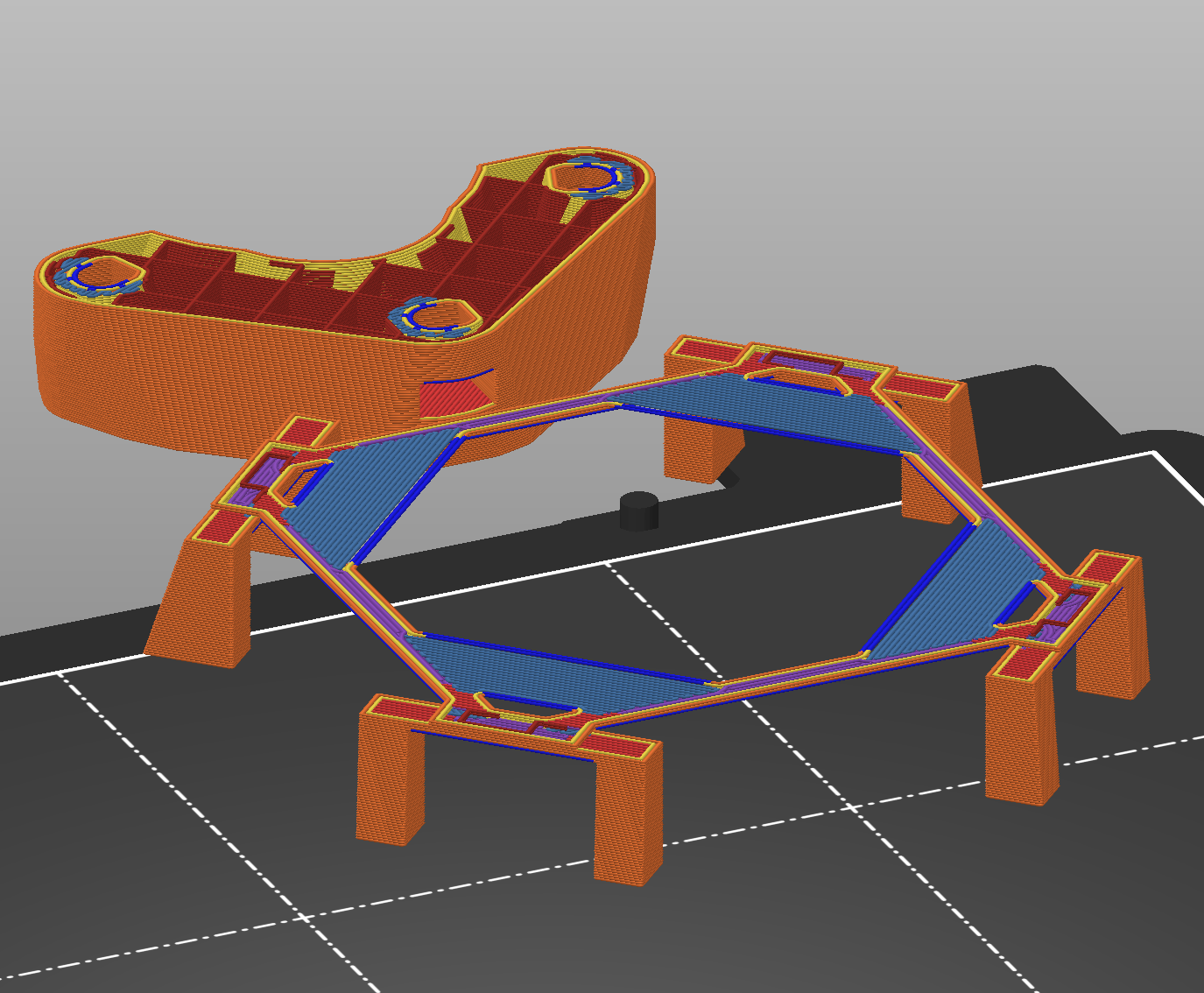
The big downside of print-in-place mechanisms is the additional design complexity. Part orientation is fixed, making avoiding supports and design for strength difficult to achieve. Especially where interlocking parts meet, it can be difficult to adequately support floating geometry. Sometimes, special break-away surfaces are placed between parts. These then have to be broken with force after printing.
Another critical topic for print-in-place design is the necessary clearance between interfacing parts. Printing multiple surfaces very close to each other can be difficult for some printers. It seems that a clearance of 0.3 mm should allow most current printers to print a design.
5. Beyond plastic - Machine Elements
After discussing the peculiarities of 3d-printed parts for so long, it is time to widen the horizon. Most functional designs will not be entirely 3d-printed, but also include other components. The largest number of them are most likely going to be machine elements. Screws, nuts, bearings, and all the other standard parts optimized for certain functions. In the following chapter, design considerations related to the use of such machine elements will be evaluated.
Nuts and bolts
Arguably the most ubiquitous machine elements are screws. For the most part, they are used to fasten different components to each other. While it is easy to just pick the next best screw and design your parts around it, there is more to it if the joint is meant to last. In traditional mechanical design, selection of screws can be a science of itself. Especially, when the screw is heavily loaded or safety critical. With design for 3d-printing, it is technically no different — but fortunately, you can usually get away with ignoring a lot of the complexity involved. Nonetheless, I think it is important to at least know the limits and some general guidance on what is good or bad for a screwed connection of 3d-printed parts.
Screw Preload
In screw theory, one of the most important values is the preload force (Wikipedia). That's the clamping force exerted by the screw at rest after tightening. For a screwed joint to work, the preload force must be greater than any forces experienced by the joint during operation.
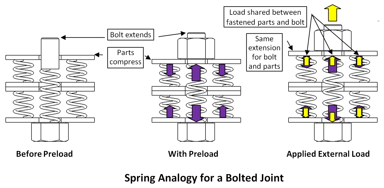
A bolted or screwed joint can be modelled using springs. Preload compresses the parts and elongates the screw. As long as the external load never becomes greater than the preload, the joint is fixed in place.
Image by Stephen Mckelvey.
In metal to metal joints, this preload is achieved by elongation of the screw. In 3d-printing and other thermoplastics applications, the joint members are much less stiff than the screw, leading to the preload mostly coming from compression of the plastic parts instead. The implication is that any of the traditional preload calculation methods are mostly useless here.
Attempting to reach the required preload force, one quickly reaches the yield strength limit of the printed parts, leading to deformation or worse. While the achievable preload is usually enough to deal with static loads of an application, it is often not possible to counteract the dynamic loads. Vibrations or shocks are usually the worst offenders.
The solution is one that's also often used for additional security of metal joints as well: Use additional screw locking measures, like lock-nuts or a threadlocking adhesive.
R5.1 — Protect dynamically loaded screws with additional locking measures like threadlocking adhesive.
Screw Length
Another noteworthy parameter of screwed joints is the length of the screw, or more precisely the length of the compressed section of the 3d-printed parts. As a rule of thumb, you should design the joint such that the screw is as long as possible.
There are two effects at play that make this a reasonable choice:
- A long screw ensures the part is preloaded entirely in compression rather than tension. When an external load is then applied, it counteracts the compression. With a short screw, the external load would just add more tension which printed parts often cannot take well anyway.
- A longer screw has to be tightened with more turns to compress the part past its yield strength. This means it becomes less likely to accidentally overtighten the joint.
Threads in Printed Parts
With screws and thermoplastics, an important consideration is the thread for the screw to fasten to. In metal applications, the thread is often simply cut into the mating part. With 3d-printed parts, the same is possible, but threads made from thermoplastics are a lot weaker. This means the threads can be easily stripped by overtightening the screw.
Nonetheless, plastic threads are an option. They can be tapped into a part if an adequately sized hole is printed and wall thickness is high enough. For bigger diameter threads (M8 and up), modelling the threads in CAD and printing them is an option, although quality of such threads is not always good. The strength of thermoplastic threads is surprisingly good — however they do not like repeated assembly and the aforementioned overtightening problem should not be underestimated.
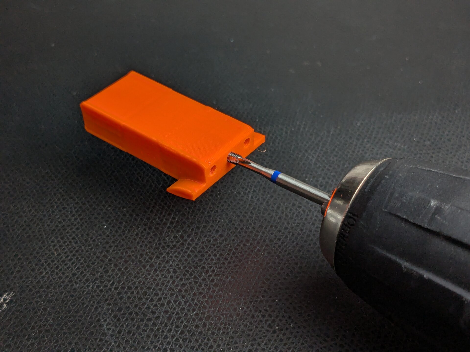
Tapping a thread into a printed part.
Rib Thread Forming
An alternative to thread tapping is to combine the previously discussed concept of Crush Ribs with a standard threaded screw. The screw can deform the crush ribs to create its own thread. This rib thread forming works surprisingly well, as demonstrated by Thomas Sanladerer (YouTube).
A part designed for rib thread forming, next to through holes with the teardrop trick discussed earlier. The rib threads start tapered to make it easy to get the screw in.
Threaded Inserts
As the downsides of plastic threads are well known from injection molding, alternative solutions have emerged. Most popular are small metal threaded inserts which are added to the part as a strong and long-lasting thread. Usually, these inserts are heat-set into an appropriately dimensioned hole.
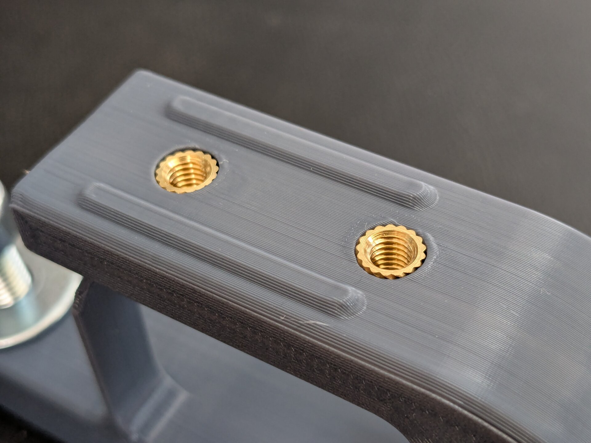
M5 heat-set threaded inserts in a 3d-printed part.
Threaded inserts are much stronger than plastic threads. They are not easily stripped by overtightening and they survive repeated reassembly many times over.
Such threaded inserts have become very popular in the 3d-printing community. Stefan from CNC Kitchen has a nice writeup about the use of heat-set inserts (CNC Kitchen).
A design limitation of threaded inserts is that they are not reliably usable for screws inserted from the back side. During insertion, heat-set inserts often push some molten plastic into the hole beneath them, preventing easy insertion of a screw from the back side. While the hole diameter can be tuned to prevent this, my experience is that this is not really portable to other 3d-printers.
Embedded Nuts
A more cost effective alternative to threaded insert is embedding standard nuts into 3d-printed parts. Usually, this is done by preparing an appropriate cutout into which the nut can be inserted after or during printing.
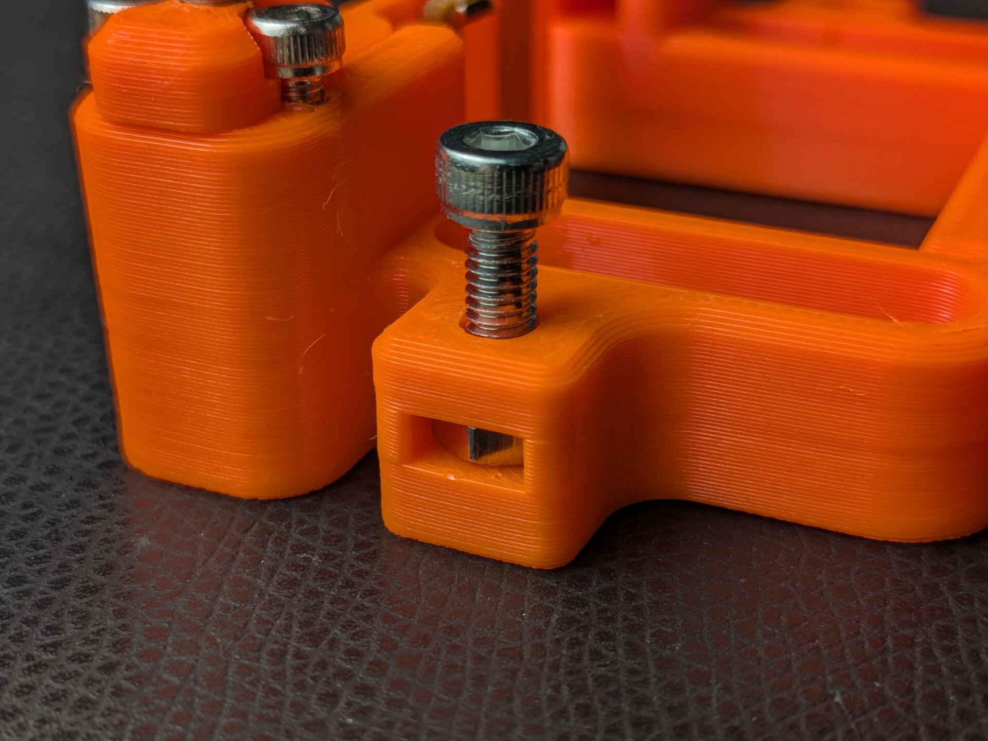
A standard M4 nut embedded into a part. It was inserted through the sideface cutout visible in the picture.
Embedded nuts are not only cheap, they are also a great alternative for the mentioned design limitation of threaded inserts. A nut is predestined to be placed on the far side of a part, making through-joints with long screws easy to realize. This also plays into the benefits of using long screws again.
Two kinds of cutouts have emerged in my designs:
- Sideface cutouts are rectangular cutouts reaching in from a side of the part to insert the nut horizontally.
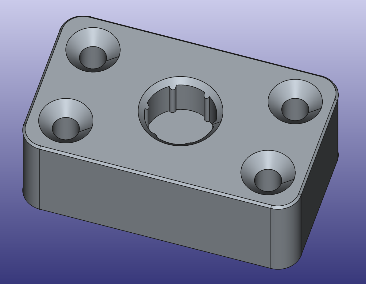
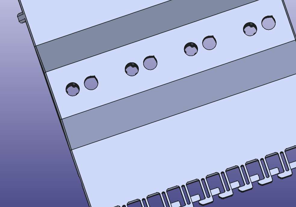
- Backface cutouts are hexagonal pockets on the exit of the screw through-hole.
Cross-section view of different cutouts for embedded nuts. On the left, the cutouts are from the side. On the right, the they are from the back of the screw.
The big downside of the embedded nuts approach is that they often fall out of their cutouts during assembly. Tuning the cutout dimensions usually does not work well — the only real solution is to "plug" the cutouts by inserting the nuts halfway through the print. This does, however, complicate the printing and assembly complexity considerably, so it often is not a desirable choice either.
Thread Strength
With all these options for adding threads and the many design considerations surrounding them, one last factor that does play a role is the strength of the threads. Lucky for us, all of the discussed options almost always have strength beyond the design requirements, with the other factors being more prevalent.
Again, Stefan from CNC Kitchen has a nice writeup on his experiments on the topic (CNC Kitchen).
Dowel Pins
Let's look at machine elements beyond screws next. While the use of dowel pins is quite rare in 3d-printed design, they should still get mentioned. In traditional mechanical design, they are the go-to solution for accurately and repeatedly locating one part to another.
As the tolerances of 3d-printing often make such accuracy superfluous, the uses of dowel pins here are limited. Additionally, such pins need an engineering fit which is difficult to achieve in 3d-printing. The best solution are the hexagonal holes or crush ribs mentioned before, or post processing of the printed parts.
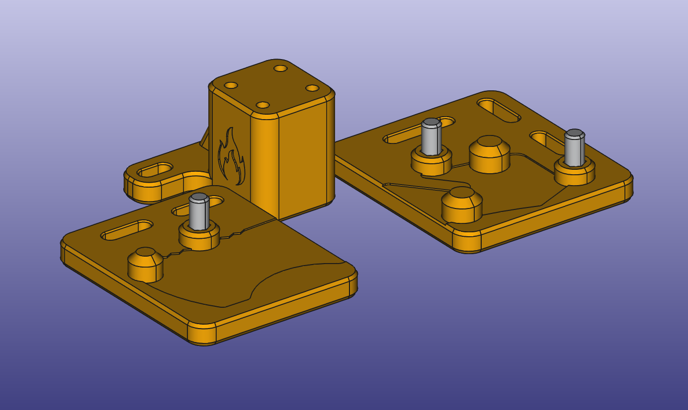
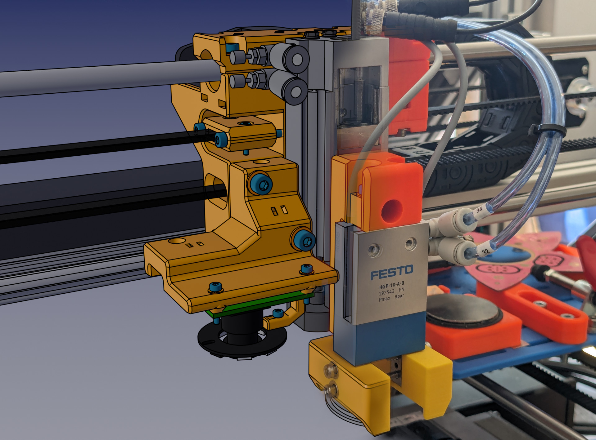
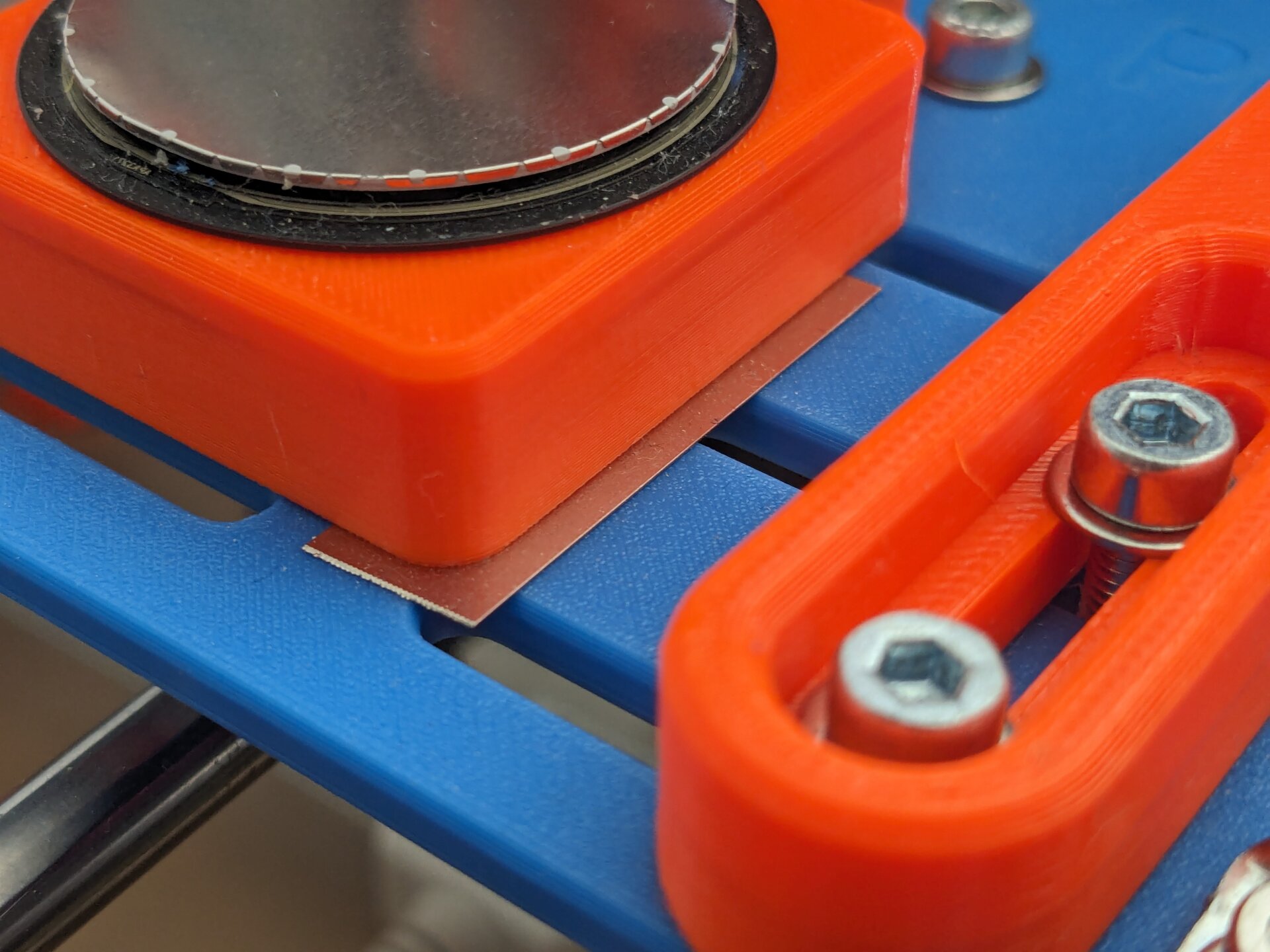
A fixture for precisely aligning a part for laser engraving. Dowel pins were used as reliable locating features.
Embedded Hardware
With the embedded nuts, we already discussed one element that can be inserted into a part mid-print. This concept can be used for many other things as well — many designs have been published that use this method in some way.
To quickly discuss the concept again, it works like this:
- In the design, a cavity is left for the component to occupy.
- During slicing, a pause is configured right before the layer above the cavity.
- When the printer reaches the pause, the hardware is inserted.
- Then the print is resumed, enclosing the hardware and often permanently fusing the part with it.
To get some inspiration, take a look at the window in this Modern Gridfinity Case by Matthew. It is made from a transparent PETG sheet that gets inserted into the print. The design even includes small tabs to hold the sheet in place, right as it is inserted. This makes for a very robust design and the result is hard to achieve with any other methods.
Of course, many other components can be inserted into 3d-prints. To name a few more:
- "Trapped fasteners" are inserted such that they cannot fall out of the part, making it hard to loose them.
- Magnets
- Metal mesh
Of course the big advantage of embedded hardware is that additional joining or fastening means can be avoided. Do, however, consider the downside that embedded hardware can only be extracted destructively and replacement is usually impossible.
Printing on Fabric
A technique that is very similar to inserted hardware, but deserves attention on its own, is incorporating fabric into a 3d-print. This produces parts with unique flexibility, especially interesting for wearable applications. For this reason, 3d-printing onto fabric is quite popular in the cosplay scene.
The gist is that a print consisting of many individual pieces is paused roughly 2 to 3 layers in. Then a piece of tulle fabric is draped across the initial layers. When resuming the print, the new layers on top will fuse into the lower ones, securing each part to the fabric.
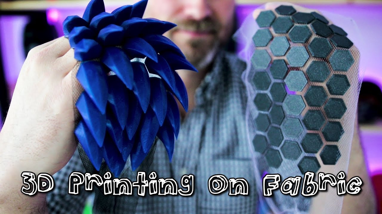
Showcase of some cosplay parts printed onto fabric.
Image by Uncle Jessy.
The flexibility of the resulting design can be finely controlled by the geometry of the solid 3d-printed shapes. Other people have already experimented with this technique a lot, for example you can check out the video tutorial from UncleJessy (YouTube).
6. Appearance
Complex Shapes
While appearance isn't the main concern of functional design, no parts should be designed without consideration of their appearance. 3d-printing uniquely allows complex surface shapes to be added "for free". Suddenly, the consideration is no longer about increased manufacturing cost, the only remaining factor is the time it takes to design such shapes.
Of course, complex shapes should still follow the basic constraints of the process — avoiding overhangs and not mandating support material. But beyond that, there is no reason to limit designs to the straight and rectangular shapes of traditional functional parts.
There are even places where complex, maybe organic, shapes have a use beyond appearance: For ergonomic design, such shapes are usually much better suited.
R6.1 — Complex shapes are often "for free" in 3d-printing. Use them to improve appearance or ergonomics.
Shadow Lines
One trick we can borrow from traditional product design practices are shadow lines. They improve the appearance of seams between mating surfaces of multiple joined parts. When two surfaces are pressed directly against each other, the result will never look great due to the imperfections on both sides leading to an uneven seam.
Shadow lines improve on this by leaving a controlled larger gap between the surfaces and hiding the actual mechanical connection behind a small lip. The larger gap is wide enough such that the small surface imperfections are no longer distinguishable. This leaves the result with a very even look without requiring extreme precision.
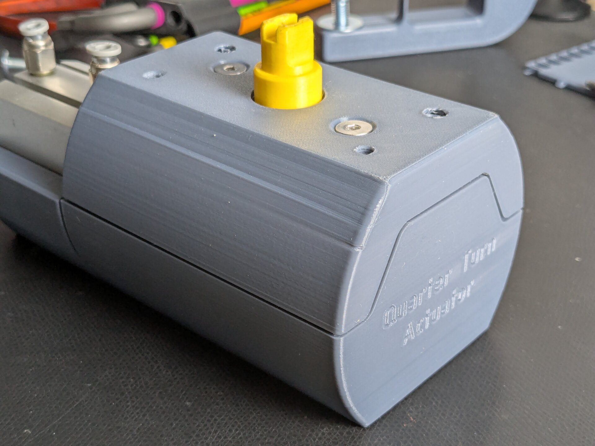
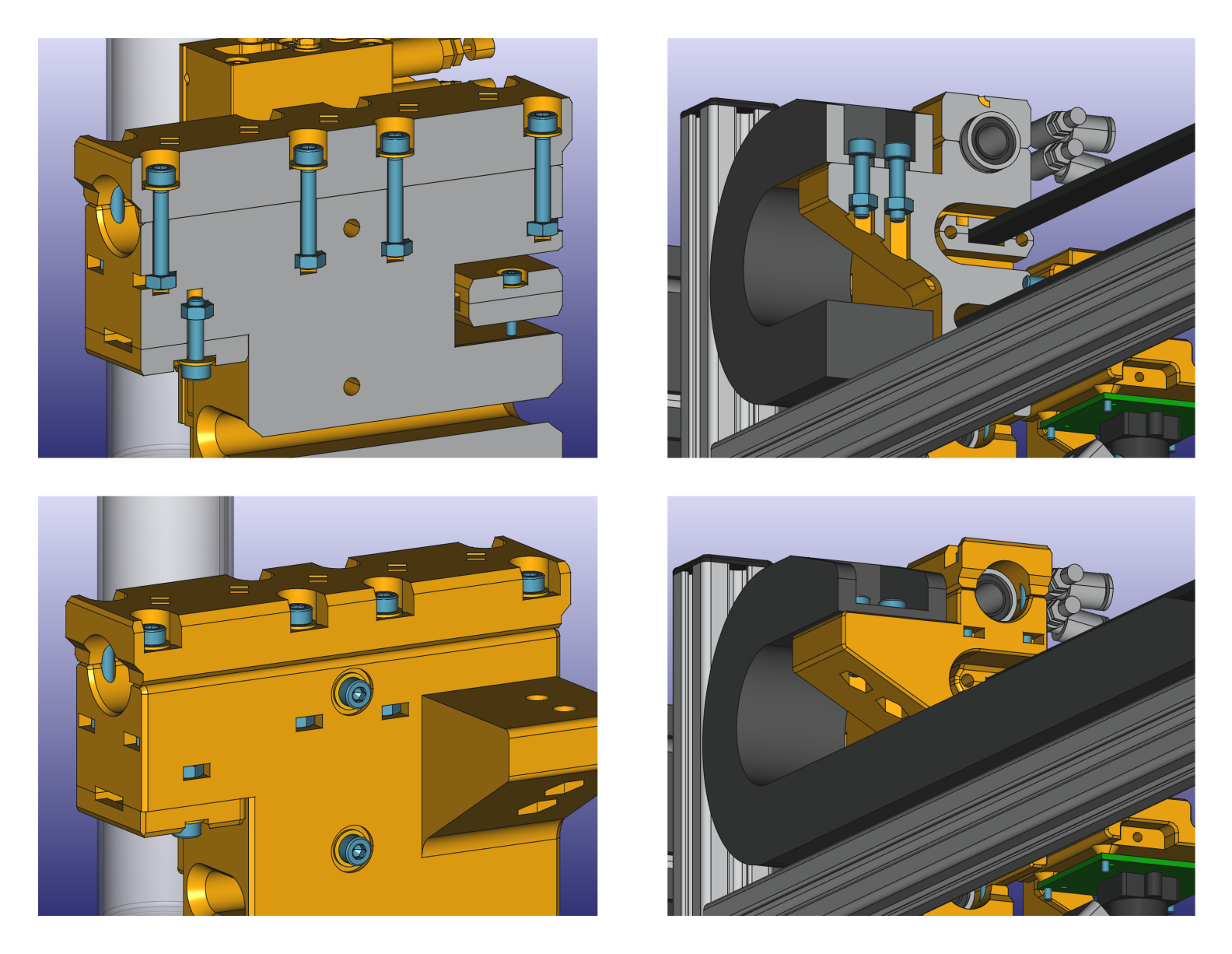
The upper and lower half of the valve actuator body have an evenly sized gap between them. The real seam is actually hidden behind the shadow line.
It may be enough to place a single lip on the shadow line to hide the real seam. If dust protection is of concern, a second lip on the inner side can transform the shadow line into a sort of labyrinth seal, providing for more than just aesthetics.
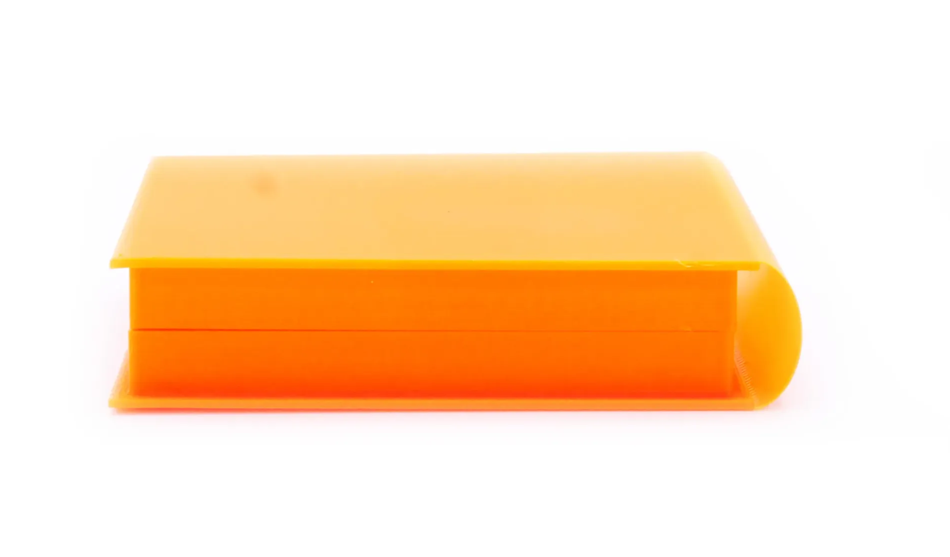
Shadow lines can also be used on parts joined at an angle, like a lid placed flat onto a box. In this case, a constant offset is left between the size of the lid and the surrounding box, with alignment tabs on the inside ensuring the lid stays centered.
The lid is surrounded by yet another evenly sized gap. To ensure it stays centered, alignment ribs on the inside locate it quite precisely.
To learn even more about this concept, Teaching Tech has made a video about the topic (YouTube).
Surface Texture
Another significant factor for appearance is surface texture. With 3d-printing, we generally do not have much control about them. Especially vertical surfaces will always prominently display the layer lines inherent to the process.
With special print beds, like textured steel sheets, the bottom surface of parts can be refined. This allows for a very clean texture, but is of course quite limited because only one surface of each part can get this treatment. Sometimes, it is actually desirable to avoid having a bed surface on a part, to keep all sides looking more even. One way to do this is rotating parts to a diagonal angle relative to the print bed.
For vertical surfaces, where the layer lines are sometimes destroying the aesthetics of a part, a trick has been developed to help hiding them. Fuzzy skin adds irregularities to each layer perimeter, building up to a surface that appears more rough, but without prominent layer lines.
Fuzzy skin also has a pleasant feel to it, if tuned correctly, which has made it a popular choice for 3d-printed grips and handles.
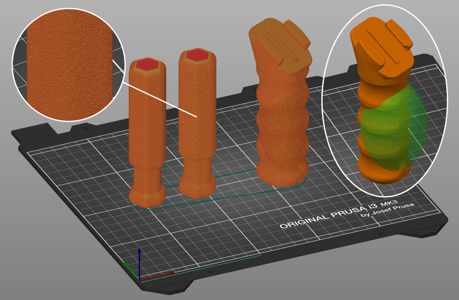
Fuzzy skin on a tool grip makes for a nice appearance and pleasant feeling while holding.
Image by Prusa Research
Printed Text
Another nice side-effect of the nature of 3d-printing is the fact that it is laughably simple to add text or symbols to a part. No need for stickers, decals, or labor-intensive engravings. There is no excuse to not add text to a printed part.
A starting point is to make it a habit to add part numbers into each part of a larger design. This way it is easy to keep everything organized. Especially when iterating on a part a lot, having the revision index printed onto it can reduce confusion quite a lot.
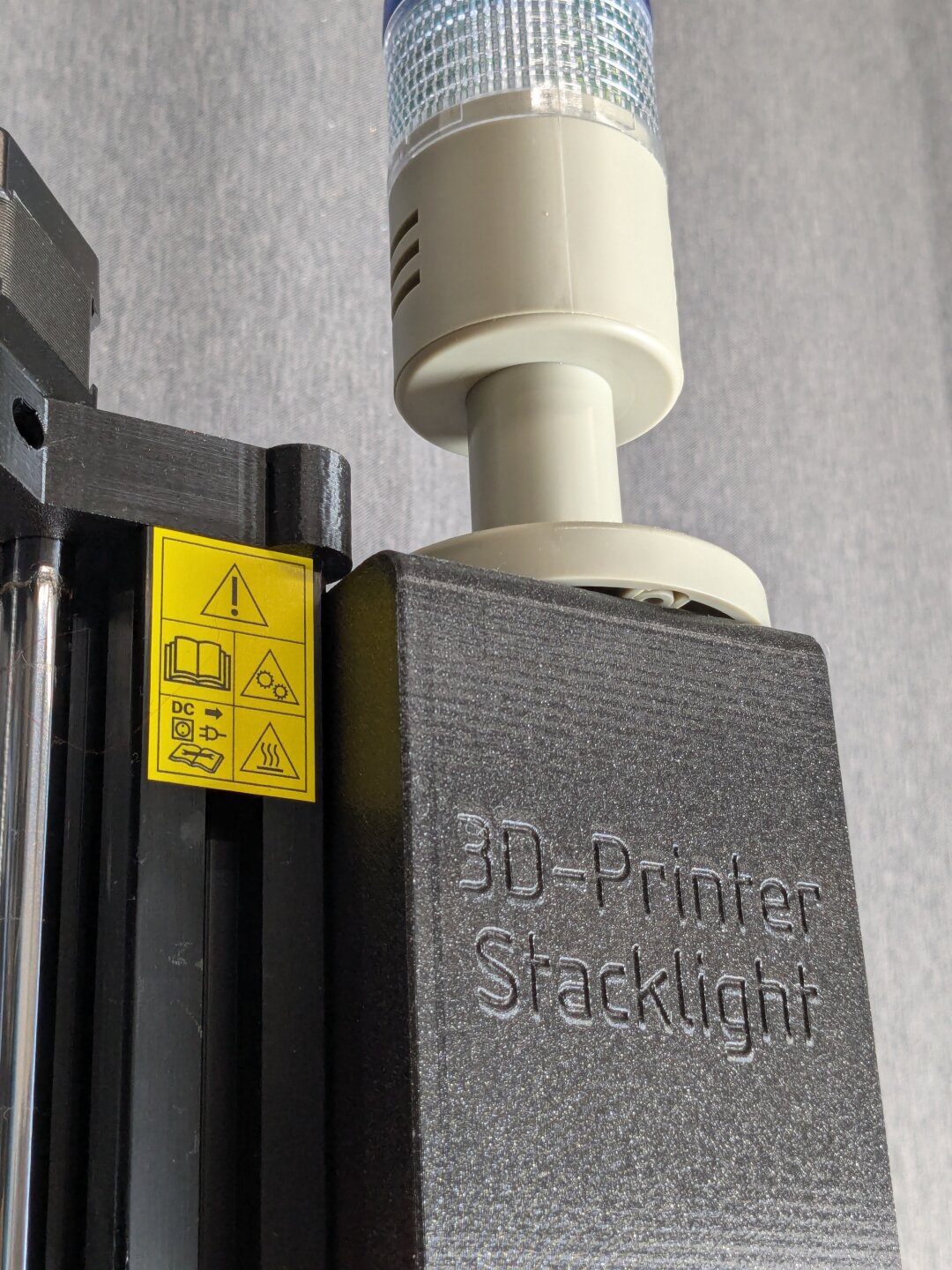
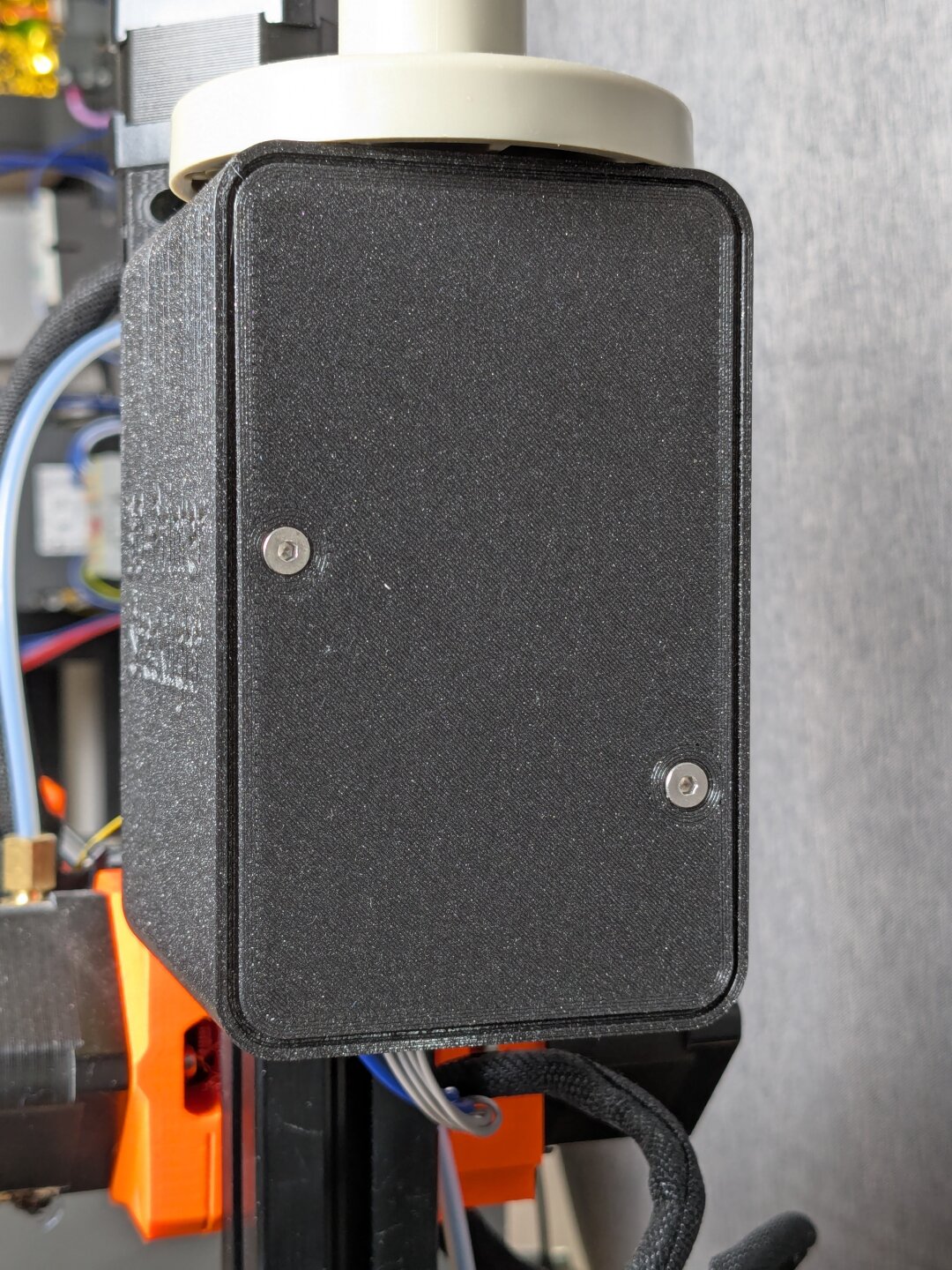
An enclosure with a label text engraved into it.
There are two ways to add text or symbols: Either the text gets cut into the surface, which is called engraving. Or the text can be raised over the surface, called embossing. For the most part, engraving leads to much cleaner results with 3d-printing. This is especially true as the font size gets smaller.
Regarding orientation, the best results will be achieved by placing the text such that it is vertical to the print surface. This way it gets printed as part of the perimeter lines where the printer can achieve the most detail.
Experience has shown that most printers can print a text with 0.6 mm minimum stroke width and engraved to 0.5 mm depth without issues.
7. Extra: Vase Mode Design
For the final chapter, I want to investigate a completely different design approach for 3d-printing — vase mode design. Inherently, the FFF 3d-printing process is not volumetric. Volumetric parts are only achieved by using lines of plastic, fused together such that a volume emerges. But whether this is the most efficient way to make use of the 3d-printing process is a question worth asking.
Vase mode is an alternative approach where only a hollow shell of a part is printed, using a single perimeter line. Instead of individual layers, the Z height slowly increases such that filament is laid down in a spiral. This has a number of advantageous consequences:
- It is very efficient because 100% of the print time is spent extruding filament.
- Due to the lack of individual layers, there is no seam in the surface.
- As the printer never stops printing, no stringing issues can occur.
- It is very fast because the least amount of plastic is used to represent a part's shape.
- It can also leads to very light parts due to the decreased filament usage.
The big downside is of course that parts become very unstable due to the missing internal support. For certain kinds of parts, especially artistic ones, this may not be a problem. Even for functional parts, like vases — where this technique got its name — the strength might already be sufficient.
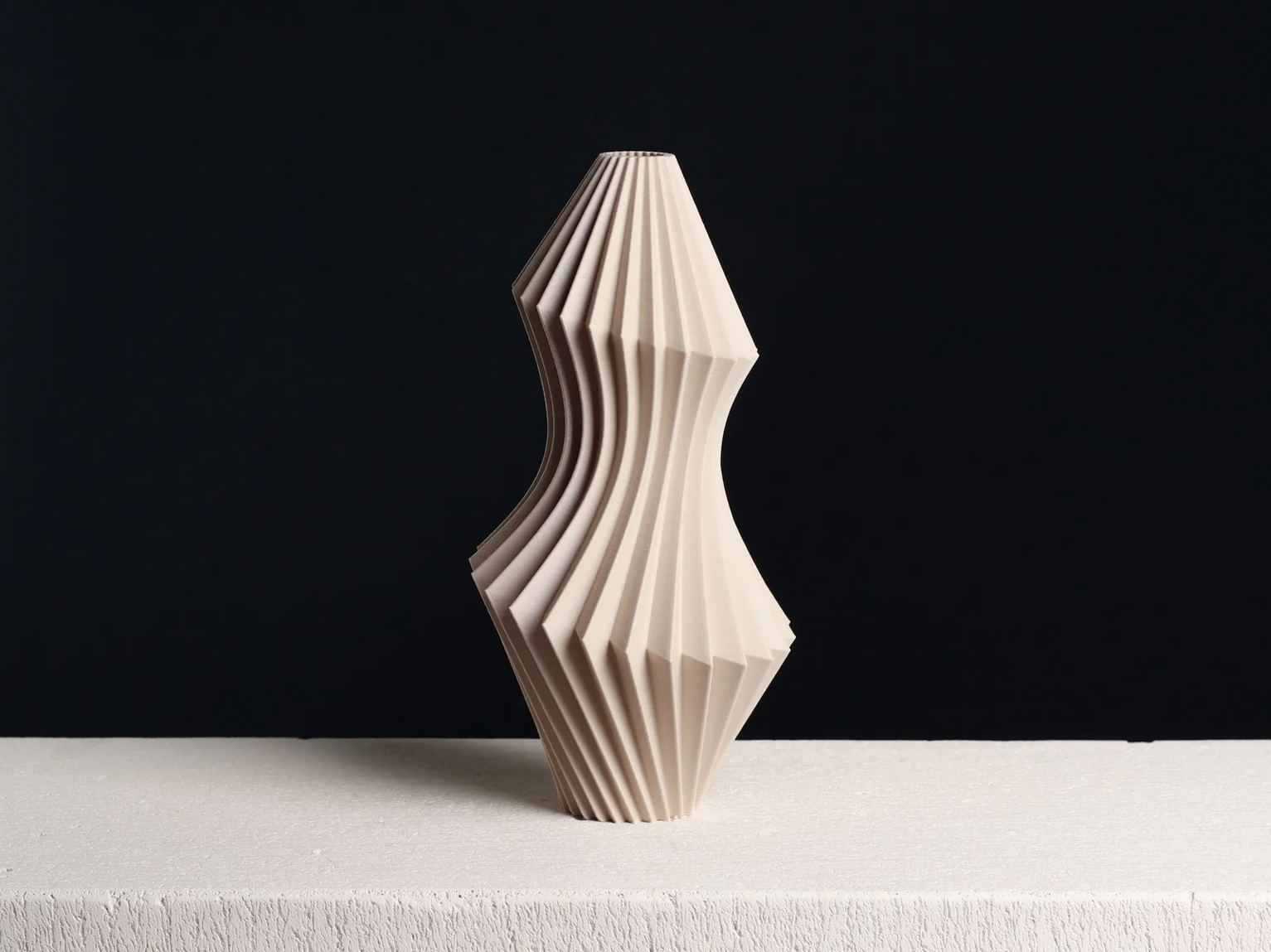
Vase design by @Slimprint
With vase mode, the most important factor to part strength is surface geometry. Surfaces that are flat or only bend in only one direction perform the worst. Intricate shapes often show much more strength. This can be seen especially with the impressive strength some vase designs manage to achieve.
Beading Patterns
What those vases achieve through style can be used for technical designs in the form of beading patterns. They describe features that are added to thin sheet-material parts to give them additional strength. CNC-Kitchen has made a video about using beading patterns for 3d-printing where this concept is explored in more detail (YouTube). There is also a german web-book going into detail about beading patterns in general (4ming.de).
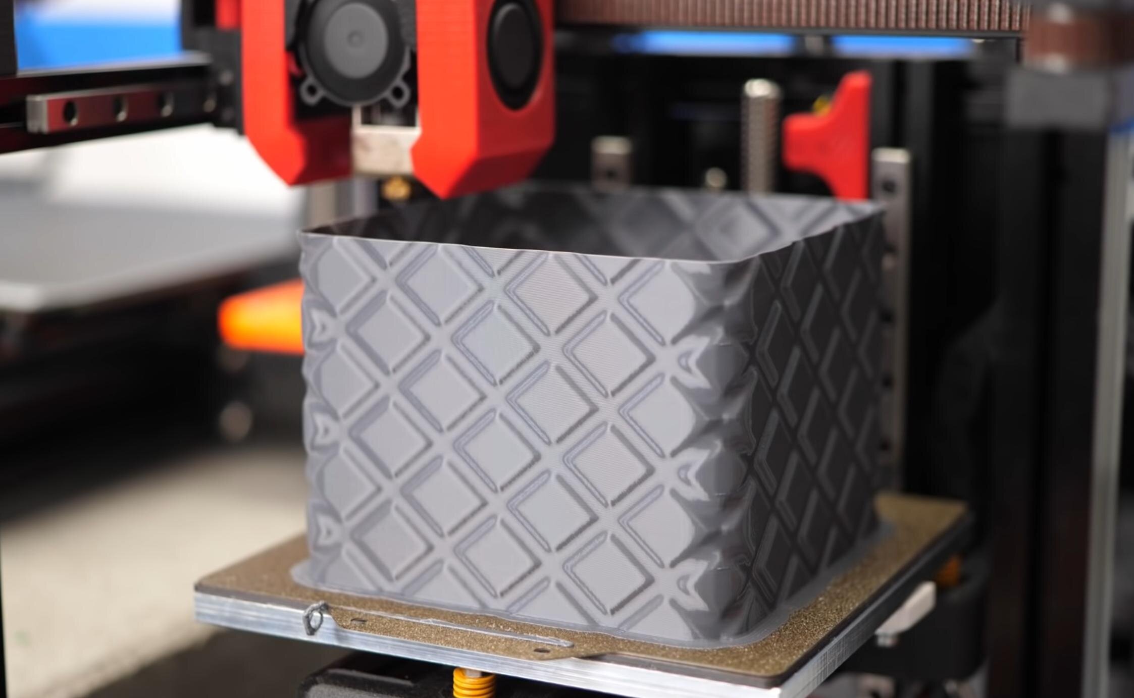
Beading pattern on a box shown by CNC-Kitchen
Unconventional Vase Mode
Interestingly, it is possible to adapt vase mode for even more uses. The trick is in viewing vase mode as a way to have very tight control over the way that a printer extrudes filament. A part is designed such that its surface perimeters describe a path for the printer which ultimately results in the intended geometry. An impressive example of this is the stackable tray designed by FPacheco (Printables).
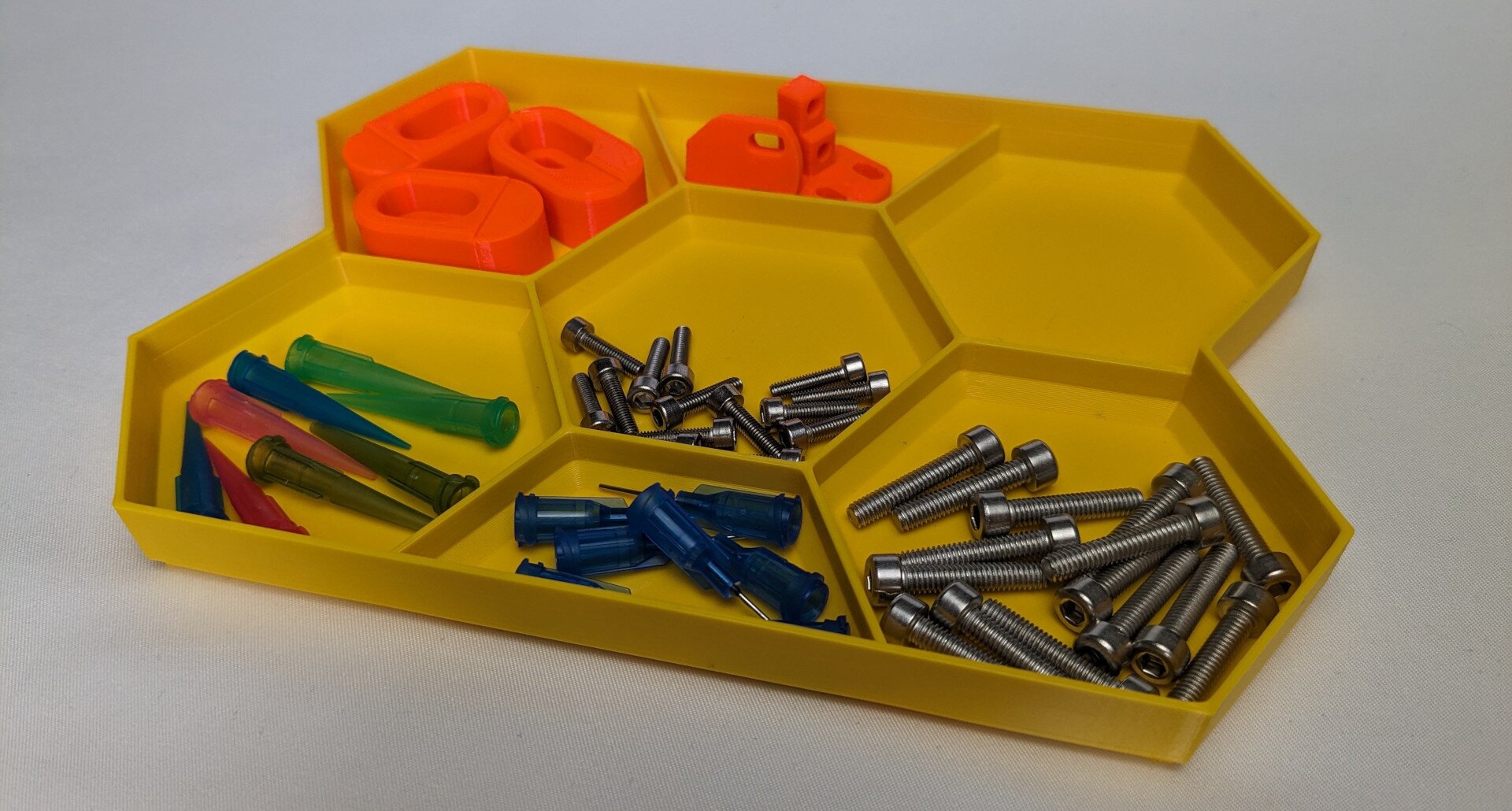
This tray looks nothing like a vase-mode part but is the result of very careful and clever design.
While the resulting part for such designs looks nothing like a normal vase mode part, it still gets the 100% print time benefit of vase mode. Especially when a part shall be produced in high quantity, this may have significant impact.
Conclusion
Alright, you have made it to the end. Below, you will find a final summary of all the design rules discussed in this blog post. Use them as a reference for your designs, as "sane defaults" when there is no good reason to deviate. But at the same time, these are no laws — there are many situations where doing things differently is the better choice. It is your job as the design engineer to make these decisions.
I have thought long about where I should publish this information. For now, placing it here on my blog felt like the easiest choice. But such "rules" live from discussion and I would love to hear your opinions and to get talking about them. If enough interest emerges, I would be interested in turning this into an "open-source book" where others can contribute their own rules or suggest changes to the existing ones. My ultimate goal is finding the best approaches for design for 3d-printing. And such a feat is only achievable by the community at large.
Checklist
As promised, here is a summary of all the rules from the blog post. With checkboxes, in case you like them :)
- Designing for Part Strength
- Manufacturing Tolerance and Part Finish
- Process Optimization
- Functional Integration
- Beyond plastic - Machine Elements
- Appearance
- Extra: Vase Mode Design